I've been using the AEC Modify - Extend and Trim commands for extending and trimming to profile objects and its been working well. I thought I would take a look the subtract tool. This one would be a useful in creating details.
It takes linework and trims out one linework from another. The two benefits of this command is that you can trim blocks with it and trim with AEC objects, such as subassemblies. To use just right click in model or paper space and choose AEC Modify Tools> Subtract select the linework you are going to subtract from (or edit) then press enter and then choose the objects that are going to subtract from the first objects selected.
Look on page 1395 of the User's Guide for a picture of how the command works.
The User's Guide is located at C:\Program Files\Autodesk Civil 3D 2008\Help\civil_ug.pdf
Sunday, July 29, 2007
Friday, July 27, 2007
Posting Elsewhere
I have a post on http://www.civil3d.com/ on VBA pipe code.
Below is a link to sample code which is similar to what I posted at Civil3d.com. The code at the link below gives the point at an offset of 10 feet from the assigned pipe's alignment.
http://fredbobchris.googlepages.com/intermittentblockoftheday
The code is in no way complete, but will provide a good starting point to create your own code for creating points from your pipes.
Thursday, July 26, 2007
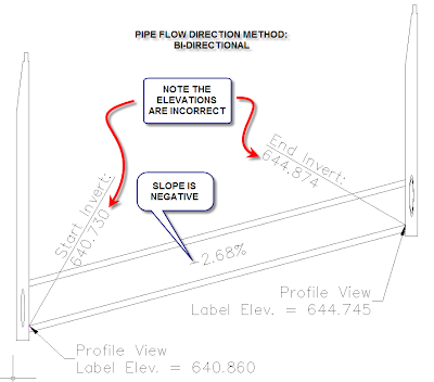
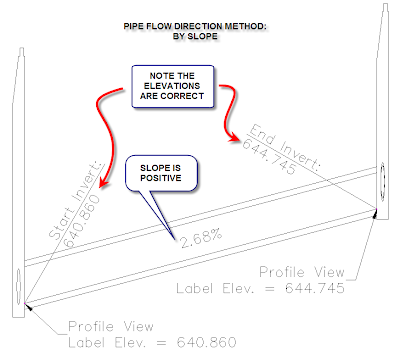
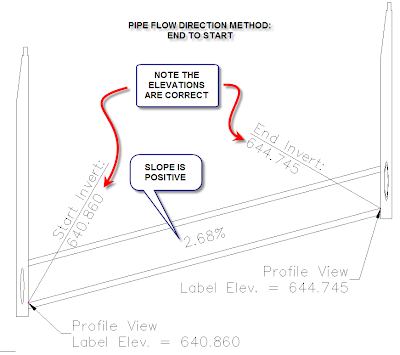
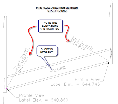
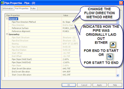
Pipes and Slopes
Here is how the various flow direction methods affect if the slope is positive or negative. Ignore the incorrect/correct invert notes, its for what's going in my AU presentation this year. The last picture indicates how the pipe was laid out and how to change the flow direction method. It can also be changed in Toolspace.


Tuesday, July 24, 2007
Command Reminders
I'm throwing away my post it attached to my computer with reminder commands and putting it here for later use.
LAYOUTREGENCTL
Set to 0 for regen each time
Set to 1 for cached view
Alt-0160 For a null character in a field (Gets rid of an error in a field that hasn't been set, ie the second line of a sheet title using the custom properties in Sheet Set Manager.)
INPUTHISTORYMODE
Changes from giving coordinates to original values typed into the command line. Don't know if it affects dynamic input. Use one of the lower values, set to 2.
filedia=1
cmddia=1
Use when the program changes these values to 0.
\X
To have a second line text in dimensions.
PSLTSCALE=1
LTSCALE=1
Just the settings the office prefers.
SCALELISTEDIT
MIRRTEXT
Changes the mirror to actually mirror text, or mirror text so the text is legible.
MAPWSPACE
Turns on and off the Map task pane.
convertpstyles
Converts the drawing from a ctb plot style to an stb plot style or the other way around.
Change all of the Blocks in a drawing to unitless:
(vl-load-com)(vlax-for x(vla-get-Blocks(vla-get-activedocument (vlax-get-acad-object)))(vlax-put-property x "Units" 0))
Copy and paste it into the command line and it will change all of the blocks to unitless. If the 0 is changed to 1 then the blocks are changed to inches, 2 is feet, 3 is miles, 4 is mm, 5 is cm, 6 is meters, 7 is km, 8 is microinches, 9 is mils, 10 is yards, 11 is Angstroms, 12 is nanometers, 13 is microns, 14 is decimeters, 15 is Dekameters, 16 is Hectometers, 17 is Gigameters, 18 is Astronomical Units, 19 is Light Years, 20 is Parsecs.
ATTSYNC - Update block attributes.
Reset User Profile and Settings: http://usa.autodesk.com/adsk/servlet/ps/dl/item?siteID=123112&id=14929107&linkID=9240697&CMP=OTC-RSSSUP01
Default Template Location: C:\Documents and Settings\Christopher.Fugitt\Local Settings\Application Data\Autodesk\C3D 2010\enu\Template
PLINETYPE Allows you to draw Polyline2D, change the values.
Friday, July 20, 2007
AEC Modify - Trim
You can use the AEC Modify Trim to edges of Civil 3D objects (or any other objects). Just choose it from the right click menu, choose the object you want to trim, then hit enter to be able to select an edge in the drawing, then select the edge in the drawing (a red line will appear indicating the edge that will be selected), then choose the side you want trimmed.
This is helpful for trimming against Civil 3D objects that you can't trim to using the normal trim command. For instance if you have a line in profile view and you want it trimmed to a profile you can do it with this command. The only thing lacking in my opinion is the ability to select a profile vertical curve as an edge.
This is helpful for trimming against Civil 3D objects that you can't trim to using the normal trim command. For instance if you have a line in profile view and you want it trimmed to a profile you can do it with this command. The only thing lacking in my opinion is the ability to select a profile vertical curve as an edge.
Tuesday, July 17, 2007
Extending Linework to an Edge
This is one that is hidden in help. When you right click in model space an option comes up for AEC Modify Tools. There is several options in the list, but the one I am talking about today is the Extend option.
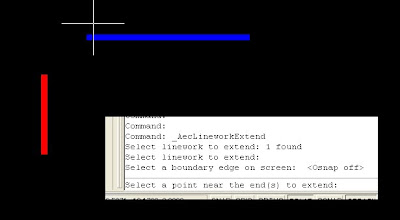
The AEC Modify Tool > Extend allows you to extend to an object, similar to the basic Autocad extend, except this one alows you to extend to a plane of the target edge. It's kind of hard to explain in word so the following pictures should show feature.
The original two lines, I am going to extend the blue line to the edge of the red line.
 Select a point near the end you want extended:
 Result of the command:

This also works the same way as the regular extend command. Another benefit of using this is that if you select multiple lines to extend you only have to click once to get all of the them to extend to the edge. No using fence, selecting each one, etc...
The AEC Modify Tool > Extend allows you to extend to an object, similar to the basic Autocad extend, except this one alows you to extend to a plane of the target edge. It's kind of hard to explain in word so the following pictures should show feature.
The original two lines, I am going to extend the blue line to the edge of the red line.

Choose the AEC Modify Tools>Extend
Select the lines you want extended, then press enter, then choose the edge to extend to:
 Select a point near the end you want extended:
 Result of the command:
This also works the same way as the regular extend command. Another benefit of using this is that if you select multiple lines to extend you only have to click once to get all of the them to extend to the edge. No using fence, selecting each one, etc...
Saturday, July 14, 2007
Sewer Lateral Code
This un-QA-QC'd code works on my one computer and one drawing that I have tried it on. It may not work for you.
For it to work it requires that all of the pipes involved have alignments assigned. See the pipe rules post for an easy way to assign an alignment as you layout a pipe network horizontally.
Once started you will be prompted to select a sewer lateral pipe. This will select the pipe and the program will use the pipe network the pipe is in. I separate the main line and sewer laterals into two pipe networks. This is so the laterals don't break the main line pipes when I am laying them out. Then select a main line pipe. It will then adjust any pipes in the sewer laterals pipe network that have an offset of +/- 1' from a main line alignment's pipe. It adjust it so the invert of the lateral pipe is at the top of the pipe. If you want to match another part of main line pipe, just adjust the code to put it where you want. The code is in two spots near the end of the code.
The code may take a while depending on how many pipes are in the network. This is mainly because I am not an expert programmer. The file can be found here, Laterals.dvb.
Thursday, July 12, 2007
Same Numbers for Parcel/Alignment Tags
I haven't actually used this, but in theory it should work. A sample style is available on the other site. Make the same numbered curves or lines have numbers in the 1000's then create an expression that divides to the number you want. So if you use 1000 and want 1 divide by 1000. The labels won't let you use the expression in the tag portion, so make the tag visibility to false, then add a text component and set the use to tag and label. Then you can have on master table to sort by length to make sure you have all of the numbers at the correct space.
Pipe Rules Fixed - I think???
I corrected the problems with the pipe rules. The corrected versions are now on the other page.
http://fredbobchris.googlepages.com/intermittentblockoftheday
Let me know if I created any other problems: fredbobchris@gmail.com
http://fredbobchris.googlepages.com/intermittentblockoftheday
Let me know if I created any other problems: fredbobchris@gmail.com
Tuesday, July 10, 2007
Pipe Rules Blues
The pipe rules I posted has some problems.
- For one if you are far away from zero, it may give you an overflow error. Just change the integer value to Double for all of the Dim, except i.
- If an start/end point doesn't project to the alignment it returns a value of zero instead of null.
I currently am looking for a solution to 2.
Sunday, July 08, 2007
Feeling Brave? Custome Pipe Rules
Have you ever wanted the assigned alignment to be relevant to where you are working at in the drawing? If you are like me you have one super duper pipe network for the sewer on your site. It can be a pain remembering to change the default Pipe Network alignment as you work to ensure that you are using the correct one, and going back and changing it can be confusing if you use the default names of Pipe - (234). These two rules will automate the process for you, somewhat. It only works if the alignments are on top of the pipe, +/- 1 unit. So if you use the center line of the road instead of the center line of the pipe it won't work.
I've written two rules for Pipe Networks. So far I haven't had any problems, but who knows what the future holds. The two rules are called Alignment and AlignmentLaterals.
Alignment: This assigns the alignment to the pipe based on the start and end stations offset values. If the start offset and end offset are +/- 1 foot away from an alignment in the drawing the alignment is set as the reference alignment.
AlignmentLateral: This assigns the alignment to the pipe based on the start and end stations offset values. If the start offset or end offset are +/- 1 foot away from an alignment in the drawing the alignment is set as the reference alignment.
The files for download have been placed here. I've only tested this in 2008 and probably doesn't work on earlier versions The file location on your computer should be in a location similar to this:
C:\Documents and Settings\All Users\Application Data\Autodesk\C3D 2008\enu\
To use the new rules, copy the existing two files with the same name to a new location as a backup. Then place the two files you downloaded into the folder you found the original two files. Restart Civil 3D, if you had it open. When you open up Civil 3D the two new rules will be available when you create rule sets, or apply it to existing pipes.
I'm not the greatest programmer so the code is probably slower than it should be. I also don't know exactly happens when you share the file with someone else who doesn't have the custom rules. I'm pretty sure it is just an error message in the event viewer.
Let me know what you think.
Friday, July 06, 2007
VBA Program
I added a vba program to this page (6-30-07). I may have not have set all of the References correctly if you are using Excel 2003 or earlier. So if you downloaded it and it didn't work this is why. I haven't fixed it, too busy trying to make it do something else related to sewer laterals.
http://fredbobchris.googlepages.com/intermittentblockoftheday
http://fredbobchris.googlepages.com/intermittentblockoftheday
Wednesday, July 04, 2007
Custom Pipe Network Rules Part I
This is just a reminder to myself how to do the first step, adding the information to the xml file which will point to a rule in the C3DPipeRules.dvb file. I would not suggest doing this until I get more information or if you have an install that you can mess around with. I don't fully know the ramifications of this or if it actually works.
- Open the C:\Documents and Settings\All Users\Application Data\Autodesk\C3D 2008\enu\C3DPiperules.xml file. I prefer the XML Notepad.
- Expand the folder heirachy under Categories, then Category, then Tools.
- You should see a list of Tool under Tools.
- Copy any of the Tool Folders by right clicking and choosing copy.

- Paste the item under Tools.

- The first thing we need to do is give the idValue, under ItemID its own unique identifier. If I remember correctly it should be a random string of numbers, so change the numbers randomly. Hopefully I will find out where you can generate the idValues, until that time changing it should work.
- Next expand Properties, ItemName. The resource is how it chooses what name it uses in Civil 3D. Choose a alpha only name for the new rule, without quotes. If you put in a number such as 155, Civil 3D will give you an error message that it can't find resource 155 but will add the resource to the list of rules as 155. If you use quotes Civil 3D will also give you an error message. Leave the src alone.
- Next expand Data, Macro and type in a name of what you are going to call the module and routine in the VBA file. I'm going to call it SetSumpDepthCustom.SetSumpDepthCustom.
- Next expand the Params and rename SumpDepthValue to SumpDepthValue2
- Change the DisplayName under SumpDepthValue2 to Sump Depth Custom.
- Set the #text to 0.5
- Now save the XML file.
- Open Civl 3D and the rule will be listed in the list of rules, in this case for structures.
I haven't created the macro yet so an error message is appearing in the Panorama window stating that it can't find the macro. This is a good sign since it looks like you can create a custom pipe rule this way and have it apply to the network. The next step is creating the macro and getting that to work.
Subscribe to:
Posts (Atom)