Ad

Wednesday, July 30, 2008

Question: VBA Structure Table

Lynn asked:

"Is there any way to create a structure table in civil 3d 2007? I also am very interested in anything you come up with on mitered end sections."

Well I've been busy with other things and haven't gotten to the MES, maybe once the kitchen is done. For the structure table it should be rather quick so I'll go ahead and do a post on this. I'm going to skip most of the beginning steps. One can find the beginning steps from my AU presentation last year. Just like the AU paper I'm using the sample code that comes with Civil 3D:

C:\Program Files\AutoCAD Civil 3D 2009\Sample\Civil 3D API\Vba\Pipe\PipeSample.dvb

Lynn indicated that the table should look like this:

structure_table

We need the Structure Name, Pipe Description, Top Elevation/Throat Elevation and Invert Elevation. Using the sample code the code for each one of the items would be:

Structure Name

sheetStructures.Cells(iRowStructures, 1).Value = oStructure.Name

Structure Description

sheetStructures.Cells(iRowStructures, 1).Value = oStructure.Description

Top Elevation

sValue = "TOP EL= " & Math.Round(oStructure.RimElevation, 2)
sheetStructures.Cells(iRowStructures, 1).Value = sValue
iRowStructures = iRowStructures + 1

Invert Elevation

sValue = "INV EL= " & Math.Round(oStructure.RimElevation - oStructure.PipeLowestBottomDepth + oStructure.PipeWallThickness(1), 2)
sheetStructures.Cells(iRowStructures, 1).Value = sValue
iRowStructures = iRowStructures + 2

So then we need to put it all together and we get what a report we can run and the structure information will be exported to Excel where we can Paste Special the data into a table in Civil 3D. The code for the invert elevation won't give the correct result if the wall thickness of the pipes entering the structure are not the same. It probably not exactly what you need, but it should get you closer than typing in all the values by hand. I posted the file here (the version is currently 2009, I will change the references tomorrow when I have access to 2007).

Tuesday, July 29, 2008

Carbon Neutral

Anybody have links to carbon neutral site materials? I'm looking for pavements, walls, benches etc... I don't think it's possible without the supplying companies buying carbon credits to offset the carbon created, but you never know.

Thanks.

Sunday, July 27, 2008

Tips and Tricks

After attending the Central Coast Civil 3D User group, I came up with some Tips and Tricks the presenters didn't use that could have been helpful. Here they are:

  • Use the command CloseAll, don't have to spend a whole lot of time having people watch you close your drawings.
  • If you need to switch between drawings, Alt+Tab works pretty well, quicker then going to Windows on the menu bar. Or if you want to use the Taskbar check this post: http://blog.civil3dreminders.com/2007/06/taskbar.html
  • Ctrl-A works in Elevation editor, so you don't have to select the first line and select the last while holding the shift key. (I remember seeing it on another blog before, just couldn't find it otherwise I would have posted a link).
  • When you offset a feature line you can offset it in both directions. Helps make it so you don't forget to do other side.

Subassemblies: Greater Than Zero

In Civil 3D 2009 some of the subassemblies you get an error when you input a zero depth. After the first few times this may get old. There is a way to get rid of it though, it takes some programming though. I haven't actually tested the code, but it should work.

The first thing you are going to need is to download a program that edits a vb.net program. Microsoft provides Microsoft Visual Basic Express Edition for free. Next open the Visual Basic Project that ships with the program. It resides at the following location (for Vista, XP will vary):

C:\Program Files (x86)\AutoCAD Civil 3D 2009\Sample\Civil 3D API\C3DStockSubAssemblies\C3DStockSubassemblies.sln

If you are using the 2008 Express Version you will be asked to update the code, go ahead and do it. Choose the Subassembly you want to change and scroll down to the part that checks the user input:

        '------------------------------------------------------------------------
'Check user input

If vBaseDepth <= 0 Then
Utilities.RecordError(corridorState, CorridorError.ValueShouldNotBeLessThanZero, "BaseDepth", "LaneOutsideSuper")
vBaseDepth = BaseDepthDefault
End If

This is the line of code that sends the error message to the Event Viewer when you enter a value less than zero. Since you probably want an error message to still exist for values less than zero change the code to read something like this:


        If vBaseDepth <= 0 Then
If vBaseDepth = 0 Then
vBaseDepth = 0.001
Else
Utilities.RecordError(corridorState, CorridorError.ValueShouldNotBeLessThanZero, "BaseDepth", "LaneOutsideSuper")
vBaseDepth = BaseDepthDefault
End If
End If

You will need to make the changes to the other user inputs and this should get rid of the error messages and make the depths an acceptably small number for Civil 3D. Build the code and replace the existing dll at C:\ProgramData\Autodesk\C3D 2009\enu\C3DStockSubassemblies.dll

Friday, July 25, 2008

Official Blog Address Change

Thanks to all you readers out there who enabled me to get some revenue from Google. It took two years, but it finally happened (I think that comes out to less than a $0.01/hour rate, less than the compensation for being an AU speaker). So I went out and got my own domain using part of the proceeds. The new web address for the blog will be:
http://blog.civil3dreminders.com/.

In the next few weeks the http://fredbobchris.googlepages.com/intermittentblockoftheday site will be moved over and reorganized to make it easier to find things for the people who actually download stuff from there.

Next week I'll be posting another Pipe Part family so stay tuned.

Friday, July 11, 2008

Microsoft Word - Tabs

I'm reviewing a document for a submittal and I've noticed that the original creator of the portion of the document used spaces to align the information that he wanted to show. While this is great for the first time, any revisions to the words causes you to have to redo the spaces. An easier solution is to use tabs. Tabs allow you to go a set distance from the last letter and align the text after the tab to be left, center, right, decimal or bar. For this example I'm going to show the center and left. the original text looks like this:

Now I'm going to add tabs instead of the spaces and get this result.
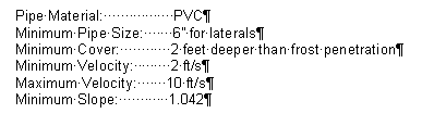
Not really the look I'm going after. I'll add custom tabs to these lines. To do this select all of the lines and double click up on the ruler or go into Format => Tab on the menu bar (don't have the latest and greatest Office program installed to see where it is on the Ribbon).

The results are below:
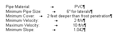
If I highlight all the rows and double click on the ruler on a tab the dialog will come up and I am able to change the tabs (if you are just in one row or highlighting one row you will only affect that one row). In this case I'm going to delete the previous tab and add a new one at 4" and make the alignment right:
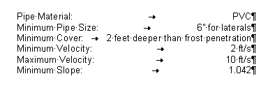
You can also move the tabs by dragging them in the ruler. They are the black characters on the ruler that look like a backwards L (alignment Left), an upside down T (alignment Center) and an L (alignment right). You can add multiple tabs to one row. This feature also works great for headers and footers if you want text both right justified and left justified.

Wednesday, July 09, 2008

Blog List

Some day I hope to make this list:
http://civilcommunity.autodesk.com/blogs/peer/

I sent feedback, but it was ignored like all of the CER reports I've sent in to Autodesk.

I must be doing something wrong, maybe I should be like Digging In... and only post once every 5 months. Or maybe I should jump ship to Autodesk, not be a peer anymore and still get to be on the list, like The Crazy World of Civil 3D and Angel's Civil 3D Thoughts. Dominick said he was going to post some more, but never did.

Remember the good old days when Civil 3D Rocks actually did Rock? Still on the list even though she moved most of the technical posts over to Civil3D.com (even says so on her blog).

I have readership, about 82 page views per day, is that too much to make the list? Couldn't be since Civil3D.com is on the list.

Maybe I should give up on the dream of being on the list and take solace in the fact that I made tenlinks recommended sites list for Civil 3D.

Monday, July 07, 2008

Another Question - Pipe Inverts in Plan

Mohammad from Canada asks:

I am just wondering if there is any way that I can find inverts along a pipe(not in structure) in plan and label it in plan.I have tried expression tool but I need to know that pipe partial length to make an equation.I appreciate your helping.

I think you are correct that you can't use expressions to do this and there is no Inquiry Tool that would provide you the elevation. There are two work arounds that I think you could use. The first would utilize the concept found in this blog post by Dana:

http://www.civil3d.com/2006/07/labeling-pipe-invert-elevations-in-a-profile-view/

It would require that an alignment is created along the pipe run and a profile along the invert of the pipe. A station offset label, with reference text to the pipe invert profile, could be used to label the point in question. While not totally dynamic (since you have to move the profile and/or label if the pipe changes) it doesn't require any external tools.

The second method would be to use/create a custom program to create the label at the location you want labeled. The most basic program could label the point in the format you require and not be dynamic. Going more advanced, a program could be written to be dynamic and the label could be programed to automatically be updated when the pipe moved.

Sunday, July 06, 2008

UPCOMMING EVENT - CIVIL 3D USERS GROUP

The first AutoCAD Civil 3D User Group serving the Central Coast. I'll be going.

From 4:00-6:00 on Tuesday July 22, RRM Design Group will be hosting a Civil 3D Users Group. Dinner will be provided. U.S. CAD Technical Specialists will be speaking on: Key New Features in C3D ‘09, Civil 3D Survey, Pipe Design Basics, and Grading Design Tools.

The User group will take place at 3765 South Higuera Street, Suite 102 in San Luis Obispo. Hurry! Space is limited!! Please RSVP to Jeff Rachel at 877-648-7223 or jeff.rachel@uscad.com.

I noticed my readership in San Luis Obispo is lacking, in order to get some gorilla advertising for my site, I'm looking for the most creative question asked of US CAD's Technical Specialist that incorporates the mentioning of this blog "Civil 3D Reminders". For the most creative question I'll give away a copy of Mastering Civil 3D 2008 signed by Dana Probert, James Wedding, Mark Scacco and Jason Hickey.

Saturday, July 05, 2008

Sample Lines VBA

I'm currently remodeling my kitchen, while my drywall is drying I'd thought I'd write some code to create sample lines at odd station intervals (ie. start at 0+08 and continue every 50 feet (ie. 0+08, 0+58, 1+08,...) for a poster on the DG. Civil 3D will start the sample lines at the start station you want, but then will sample at every 50 foot section (ie. 0+08, 0+50, 1+00,...). The code modifications are based on 2009, but should work with 2008 (just haven't had a chance to test it).

Since we don't want to start from scratch I'll start with the sample code that comes with the Civil 3D, in this case I'm going to start the section line sample code: C:\Program Files (x86)\AutoCAD Civil 3D 2009\Sample\Civil 3D API\Vba\Section\SectionSample.dvb (use vbaman to load the file, and choose the Visual Basic Editor to open it).

image

So now we need to have the user select an alignment and check to make sure they selected an alignment. The following will code will accomplish this:

        ' Have the user select an alignment
Dim oAcadObject As Object
Dim entbasepnt As Object
ThisDrawing.Utility.GetEntity oAcadObject, entbasepnt, "Select an alignment: "
If (TypeOf oAcadObject Is AeccAlignment) Then
oAlignment = oAcadObject
Else
MsgBox("You didn't select an alignment.")
Exit Sub
End If

If the user doesn't select an alignment the program will end and they will need to restart the routine. Now we need to edit the CreateSampleLineGroup code in the SampleLine module. Below are the parts that can be deleted or modified to match your template.

image

Since we deleted some lines that created a style and used that one, we need to add in the what the program should use. I'm just going to use the first one in the list under Toolspace for the respective type. You could modify the code to use the type you want. The code is below and should be placed above where the oSampleLineGroup is set:

        ' Add a new group to hold the sample lines we will make.
Dim oSampleLineGroup As AeccSampleLineGroup
' Set the oGroupPlotStyle as the default
Dim oGroupPlotStyle As AeccGroupPlotStyle
oGroupPlotStyle = g_oDocument.GroupPlotStyles.Item(0)
' Set the oSampleLineStyle as the first one on the list
Dim oSampleLineStyle As AeccSampleLineStyle
oSampleLineStyle = g_oDocument.SampleLineStyles.Item(0)
' Set the oSampleLineLabelStyle as the first one in the list
Dim oSampleLineLabelStyle As AeccLabelStyle
oSampleLineLabelStyle = g_oDocument.SampleLineLabelStyles.Item(0)


Next we need to prompt the user for the various values he/she wants to sample for. The following code is vary basic and could be improved greatly with the use of a form similar to the one that is in Civil 3D. The values for the starting station and ending station are just for information and won't be used as a default, it just made it easier to check to make sure the program worked as intended:

        ' Prompt the user to provide a swath width right
dSwathWidthRight = ThisDrawing.Utility.GetReal("Enter swath width for right side: ")

' Prompt the user to provide a swath width left
dSwathWidthLeft = ThisDrawing.Utility.GetReal("Enter swath width for left side: ")

' Prompt the user for the starting station
dStationStart = ThisDrawing.Utility.GetReal("Enter starting station " & Math.Round(oAlignment.StartingStation, 2) & ": ")
dStation = dStationStart

' Prompt the user for the ending station
dStationEnd = ThisDrawing.Utility.GetReal("Enter ending station " & Math.Round(oAlignment.EndingStation, 2) & ": ")

' Prompt the user for the station interval
dStationInterval = ThisDrawing.Utility.GetReal("Enter station interval: ")

So now that we have the information we can now add the various stations the user wants. First I will create a default naming convention for the sample line name since they have to be unique and will use an Do While statement to go through the sections that need to be revised/added at the location to add a sample line based on location:

        Dim sSampleLineName As String
' Cycle through the station range and add sample lines
Do While dStation < dStationEnd
sSampleLineName =
"SampleLine-" & dStation
Call oSampleLineGroup.SampleLines.AddByStation(sSampleLineName, dStation, dSwathWidthLeft, dSwathWidthRight)
dStation = dStation + dStationInterval
Loop


This code is the basics to get the intended results as stated above. The program would need plenty of error catching to work perfectly. For instance if you run it again with the same starting, ending and station interval you will get an error message since you can't have sample lines with the same name. To get this to not happen you would have to delete the other sections, or prompt the user to see if he/she would want the section replaced. You would probably also want default values to limit the amount of typing that would be required by the user.

I placed the dvb file on my companion website, under the 07-05-2008 date. If anyone wants a more polished program I could provide it for a nominal fee, but the above code should work in a pinch.

LinkWithin

Blog Widget by LinkWithin

Ad