Ad

Wednesday, October 29, 2008

Expressions - Radians

This is it my 200th post and a reminder to myself that when using angle values in expressions they are in radians. A complete circle is 2pi. A half a circle is pi.

An example how this can used may be found in this link. http://style.civil3dreminders.com/checkrightorleft

This example uses expressions to indicate if the curve at the PI goes to the right or the left.

Tuesday, October 28, 2008

Civil 3D User Group Meeting in SLO

There is going to be another SLO Civil 3D user group meeting on November 12. This link has the information: http://fredbobchris.googlepages.com/SLO-Nov122008.pdf

If you do attend, I'm going to attempt to give away my signed copy of Mastering AutoCAD Civil 3D 2008 again. If you see me and I'm holding the book just ask for it and its yours. I've got to make space for my 2009 version of the book.

Monday, October 27, 2008

Elevation Analysis - VBA Style

One of the items you can't seem to store in your template is how the Elevation analysis is applied to a surface. If you find yourself always changing the values to a default, this post may help you become more productive.

The first thing we need to do is select a surface. This is how I did it:

image

Once we have a surface then you can create the elevation analysis regions you want to the surface. This routine assumes that one has not been applied yet. If you already have created one, you may want to remove the existing one first or modify it.

image

In the sample above the code is creating 2 regions. If you want more just change the value. Once the regions are created we can change the properties of them. We do this by creating a new SurfaceElevation object. Next we have to set the values that we want to use for the regions. Here is the code to do it.

image 

Follow the pattern and do the same for additional regions. Like most of the examples on this site, no error catching has been added, such as On Error Resume Next line to get rid of an error message if the user didn't select an object. Have fun.

Wednesday, October 22, 2008

HEC-RAS Extension - Bonus Feature

Autodesk has provided the HEC-RAS export report for subscription members, now get the Civil3D Reminders Bonus Feature for the extension. Sure you have to do most of the work yourself, but you don't need to fork over money to get it (unless you want too, I won't say no).

In the current report you only get to have the flow direction of the stream go one direction, from a lower station to a higher station value. With the Civil 3D Bonus Feature you get to choose if you want the stream to go the opposite direction. The first step is to add a CheckBox to the AlignToHECRAS form. To open the form double click it in the Project list on the left side of the screen. Then use the Toolbox to add a CheckBox, it fits conveniently below Reach Alignment box. Change the name of the CheckBox in the properties area under (Name) and enter a caption that indicates that the flow direction of the stream will be reversed if the CheckBox is checked.

image

Now that we have created the CheckBox we can modify the code to reverse the information that is written to the report. HEC-RAS determines the flow based on how stream is drawn. It assumes the first point is upstream and the rest are downstream from it. The code below reverses the information, moving the first point to the back and the last point to the front.

image

Once the code is finished you are ready to run the report. Once imported you will want to check the data, in accordance to the HEC-RAS user manual, especially to see if the sections are drawn correctly. If they are not use the Reverse Stationing tool to reverse the cross section. HEC-RAS assumes the cross sections are entered from left to right looking downstream. If after using the tool the cross sections are backwards, let me know and I'll see about modifying the code to get them to come in correctly.

image

Here are the results of running the revised code with the CheckBox checked and unchecked from HEC-RAS:

image image

Sunday, October 19, 2008

Tc Inquiry - VBA

One of the tasks engineers have to do is Tc calculations. While Civil 3D lets you use label the overall length of a feature line/3DPolyline it does not let you have access to the start and end point elevation of the line. If access was allowed to the start and end point elevations you could use an expression to do the Tc calculations. This post covers how you can calculate the Tc using VBA. The code adds a text label with the Tc value.

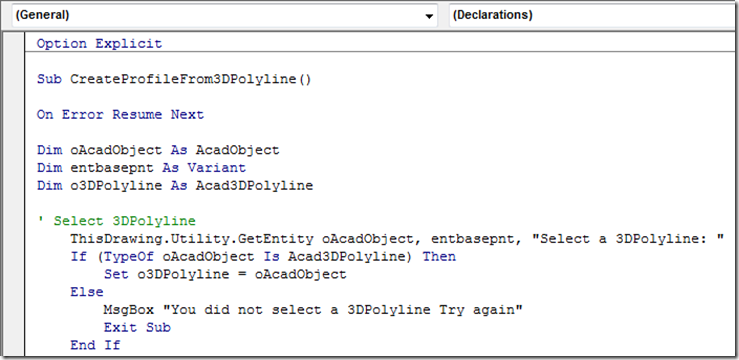
The first thing we need to do is to have the user select a 3DPolyline. The code to do this is shown in the picture below.

image

Now that we have the 3DPolyline we can process it to get the required information from it.

image

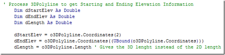
As shown above getting the ending a starting points is rather easy. The vertices information for a 3DPolyline is contained in the Coordinates part of the object, which is an array type object that starts at 0. The starting elevation is the second value since 0 corresponds to the X value of the first vertex, 1 corresponds to the Y value of the first vertex and 2 corresponds to the Z value of the first vertex. To the the last vertex information we need to determine the number last value in the array. The Ubound() provides that information by giving the number of the last value in the array. The length value of the 3DPolyline is the actual length of the 3DPolyline. Since most methods of Tc was created before widespread use computers the length needed is the 2D length of the line. To get this we need to make a copy of the 3DPolyline and then set all of the Z values in the coordinates array to 0. There may be a better way to do this, but this is the way I thought to do it. If you think you should use the 3D length you skip adding the code below.

image

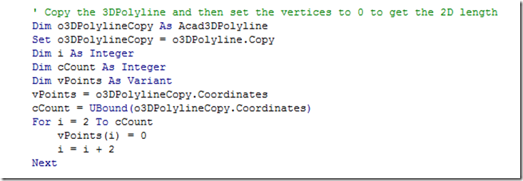
The code takes all of the vertices and adds it to an array then sets the Z values of the vertices to 0. If you can follow patterns you should recognize that every third value is the Z value for a vertex. So that is why at the For i = 2 part of the code it starts at 2 and then process every third value. The Next adds 1 and the i = i +2 has the code move every third value.

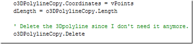
So now that we have modified the vertices we need to set the vertices of the copied 3DPolyline to the modified values. The change is done below and the length is gotten and then the copied 3DPolyline is deleted.

image

Now we need to calculate the slope, but before we do that we need to make sure we get a positive slope (unless you have water that goes up hill). The if then statement does this in the code below. The Tc value is then calculated.

image

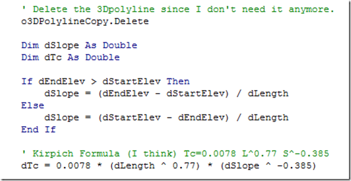
The Tc formula may not be the one you use, or you may have to use different constants contained in the 0.0078 value. So make sure the Tc formula is the one you have to use.

So now that we have a Tc value lets add it to a text label and place it where the user selected the 3DPolyline. The code to do that is below.

image

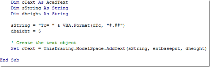
The text height is hard coded in the above example, so if you want it to be something else go ahead and change it.

This example assumes you use the waterdrop feature in Civil 3D to generate the line so you can ensure that the 3Dpolyline slopes from a high point to a low point. If you use an alternative method to create the 3DPolyline you may want to add a check to make sure the 3DPolyline slopes in one direction (such as drawing a polyline and then using the surface drape tool). You can also add the other information used in the calculations to the label or export the information to an Excel spreadsheet.

A copy of the completed code may be found on this page of the style site.

LinkWithin

Blog Widget by LinkWithin

Ad