A place to put reminders on how to do things or commands that I will use rarely, but are useful to know.
Monday, December 31, 2007
Why Microstation?
First off I work for a leading provider of consulting, engineering, and technical services worldwide (yes, I did copy this from the website). We have many clients with a diverse set of requirements on how their work is performed. My learning Microstation has more to do with meeting the clients requirements than seeing which company has the best software.
If I really wanted to see what product is best, I think I should use the most current Microstation products, mainly PowerCivil. But since client requirements preclude this I don't think any of my posts should be taken as which is best and which one to use. For instance Microstation V7 has a limitation on how many levels (layers in Autocad terms). In V8 an larger amount of levels are allowed. Obviously V8 would be better to use, but I am precluded from using it due to client requirements. From what I have heard Microstation has the same version problems that Autodesk has.
Since I won't have access to the most current Microstation version of the software I don't think I can make a valid assessment of what is better. I did request a version of the most current version of Microstation, but haven't received it after two or three months and have given up on ever seeing it show up.
Friday, December 28, 2007
Microstation - Installed Today
I went to help to see if there are some tutorials, I couldn't find any so I just clicked on things and tried to see what buttons did. I didn't have much luck figuring things out. Hopefully I can find some tutorials in the future and learn how to use the program.
Wednesday, December 19, 2007
Slope Arrow Direction
A coworker was looking for a method to have a slope arrow always point down hill. He saw the method at AU, but couldn't find the handout which had it. I found the method on the AUGI web site. Since I will probably need this in the future, and won't remember that I found it on the AUGI web site, I'm going to post it here in the form of a surface slope label.
The formula to use in the expression is the following:
IF({Surface Slope}<0,0,pi)
Put the expression in the arrow component rotation of the surface slope label, see below:
The value of pi is used because the rotation value is in radians. If you want the arrow to go the opposite way, just reverse the second 0 and pi. Now if you use the label the slope of a surface the arrow will always point in the direction you want, but the slope will be positive or negative. You could always drop the sign of the label, but that would be too easy. Another way to do it would be to add another expression:
IF({Surface Slope}<0,-{Surface Slope},{Surface Slope})
Tuesday, December 18, 2007
Sustainable Design?
Right now I am watching House Hunters on HGTV. It's a show where a couple is followed through their house search. They live in Chicago, so the density portion of sustainable design has been met. But much of what they are looking for in a new place to live goes counter what sustainable design strives for. From what I can tell here are their requirements:
- Parking for their car
- Not being close to a subway (mass transit).
- A larger living space (than their current living arrangement's)
The requirements largely go counter to what sustainable design strives for. The density is supposed to reduce the need for a car, but they need to commute regardless. The housing is supposed to be near mass transit, but the noise created by the mass transit is not something they want to deal with. Well a larger place isn't really related to sustainable design in land development, but it does affect the energy use in the building. A larger place typically requires more energy use, but the energy use of the building didn't appear to factor into their decision. I guess it may have come into play if one of the houses used it as marketing tool to make the a condo/house more attractive.
I guess my real problem with sustainable design is that it's being sold as something people want, but if you watch people and their decisions they mostly (or large portion of the population) don't factor it in their decisions. I suppose the people who put together the sustainable design want the designs to be that way? Or do they too not live in houses that meet sustainable design? I know I don't, but I don't think that is going to stop me from working on sustainable design projects and assisting my company in marketing it to potential clients. Isn't that all it will be in the end, a marketing tool without much real meat behind it?
Friday, December 14, 2007
VBA: Export to Excel and Then Some
On the 6-30-2007 date on this website I previously posted a VBA macro to get pipe and structure quantities from a drawing. This is an example of how to export information to Excel and then modify it. So lets say you thought it was neat, but wanted to change what it did in Excel and didn't have much VBA experience. An easy way to see what direction you should go in would be to use the macro recorder in Excel. To get to the macro recorder in pre-2007 its under Tools => Macro => Record Macro. In 2007 you will have to go to the Microsoft symbol and select Excel Options. Under popular, check the "Show Developer tab in the Ribbon".
In the Developer tab use the Record Macro button and press Ok when the Record Macro dialog box pops up. Excel will now keep a record of all of the movements and commands you do. Do what you want the routine you are creating to do. When you are done press the Stop Recording button (before 2007 it is on toolbar that pops up when the recording starts, in 2007 it is on the Developer ribbon). Once you stop the recording choose the Visual Basic option to see the code that was created.
The code Excel created is in the next picture. It will take a little work to make AutoCAD do the commands in Excel, but the sample mentioned earlier should start you on your way or take a look at the AU class I did which has another example.
Microstation
Vote in the poll on the right, majority rules in this case. The poll will be open for a week.
Tuesday, December 11, 2007
VBA: Create Existing Ground Profile For All Alignments in a Drawing
I saw a post today in the Civil 3D DG that reminded me that I wanted the functionality to create existing ground profiles for all of the alignments in a drawing. I don't want to wait for Autodesk, I want it now. Well this is how I created it today.
As a starting point I am going to be using a renamed copy of the VBA profile sample: C:\Program Files\AutoCAD Civil 3D 2008\Sample\Civil 3D API\Vba\Profile\ProfileSample.dvb
To start I'm going to go to the Profile module (CreateProfile macro) which contains the code to create profiles. Since it creates both an existing ground profile and finish grade profile I will delete the code portions that relate to creating the finish grade profile. I don't want to create a profile so we will delete that code also. Since I am doing this just for my own use I will delete the portion that gets the collection of profiles. The picture to the right is what I was left with.
Since you probably have surface you want already in the drawing we will change the surface to one that you select in the drawing. To do this use the following code:
' Get the specified surface.
Dim oSurface As AeccSurface
Dim oAcadObject As Object
Dim entbasepnt As Variant

ThisDrawing.Utility.GetEntity oAcadObject, entbasepnt, "Select a Surface: "

If (TypeOf oAcadObject Is AeccSurface) Then
    Set oSurface = oAcadObject
Else
    MsgBox "Selection was not a surface"
End If
Instead of using the default name that the sample uses I will use the alignment name and then the surface name. To do this I will Dim a string and then store the data name in the created string. Make sure to replace the instance of PROFILE1_NAME with the string variable created, in the posted code I used ProfileName. So that is all of the changes that need to be made to the profile module. Next we will select all of the alignments and then send the alignment name to the CreateProfile Function to create the EG profiles.
As a starting point I will be using the PerformProfileDemonstration code in the Subroutines module. First I will delete all of the routines I don't need (I will keep the CreateProfileView code in case I want to use it later in another post, but I will comment it out so it doesn't call the code). To select the alignments we will use a snippet of sample code from the pipes sample. It essentially looks at all of the objects in the drawing and checks to see what type of object it is. I will be doing this change in the subroutines module. So to the left is the code I finished with.
Now if you hit play, you would find that I cut to much and made a bunch of mistakes, but hey its free post. The first thing we want to do is make sure I declared all of the variables correctly. Once those have been fixed I will need to add back in some of the code I deleted earlier. Mainly it was the Profiles collection and the name of the style. For the style I used Standard, but you could replace the name with any that you have in your template.
Now that everything is fixed I hit play. I got the results I was after, but I had to select the surface multiple times. To prevent from having to select the surface every time I will pull selecting the surface out of the profiles and put it into the subroutines macro. To pass the surface from the subroutines macro to the Profile macro I needed add oSurface As AeccSurface to the title of CreateProfile and then add it to where we call the create profile function.
The finished sample can be found here with a date of 12-11-2007. If you run it more than once it will just overwrite the existing one and will not create a new one, but if you have a finish grade profile with the same name it will overwrite that one. There is some more work to be done to make it error free, but should work for my purposes and only took about 2 hours including the time to write this.
Monday, December 10, 2007
Views and Sheet Set Manager
I usually forget to use this but you can use Sheet Set Manager to take model space views from one drawing and place it into the layout of another sheet. To do this open sheet set manager and go to the Model Views tab.
Right click on the Add New Location... and add a new location. Select the folder with the drawing(s) you want to access the views in. Expand the drawing with the view that you want to add to another sheet's paper space.
Once it is expanded drag the view into paper space or right click and choose Place on Sheet. Now you can place the view on the sheet at the default scale or right click and choose the scale to add the view as. The command adds the referenced sheet to the current drawing as an xref.
Sunday, December 09, 2007
Views
When you open a drawing you can specify what view the drawing opens to. Just open the drawing using the Open command in windows. Check mark the Select Initial View option in the dialog box:
Once you select a file to open another dialog box will come up to let you choose what view you want to open:
Select the view you want and then press OK and the view you chose should be the view you see when the file opens. The M indicates model space and if a P shows up it indicates a paper space view.
Friday, November 30, 2007
Non-Breaking Space
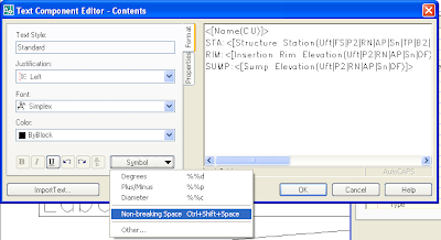 An example of a label that utilizes it may be found here, under the date of 11-30-2007. It needs some work to be usable, but should point you in the correct direction.
Point Transformation
Properly set the current drawing units and coordinate settings, located within the Settings tab of the prospector. (i.e. Where in the world are you or where were your points shot?)


Check results!

Yep, it's that easy!
Alternatively you can import your points from your handheld GPS unit using a drawing that is setup for Lats and Longs and then "Export" using the "Point File Format" that you created above.
BAM! You now have a point file that is on the coordinate system that corresponds to your design coordinate system.
AU Reminders
First I would like to introduce my coworker Jason to any of the regular viewers of my blog. Jason has helped me and the office I work in to make the transition to Civil3D from Land Desktop. Hopefully you will find Jason's reminders as helpful as you find mine. I would also like to thank Engineered Efficiency for the free shirt and Mastering Civil3D book, even if the book was a mistake on the part of one of the EE team members.
For the rest of the post it will be a reminder to me of my AU experience. The whole point of the blog was to put what I found out about Civil 3D and Map and Autocad here so I could remember what I figured out and how to recreate it. I usually regret finding something out and then having to do it over and not remembering how to do it. This blog seemed like a better container then the office network or my home computer, I just have to remember to use it.
First lesson I learned at AU this year is the a benefit of being a presenter is the ready supply of water and the quick access to the Internet in the Speaker Ready Room. Don't have to wait for a free computer in the common areas. You also have the opportunity to talk to the notables who bring you Civil 3D.
The second lesson I learned is that you should do a good job of doing your description of your class. I got this from feedback from my coworkers comments and my own presentation experience. My coworkers found that some classes didn't deliver on the description of the course. I think my problem was the exact opposite. I think I didn't convey the complexity of my presentation. I did submit it as an advanced course, but I lost half of my audience by the end. I did hear some positive feedback from some of the people who remained to the end. I probably should have stressed the modifying of rules rather than just covering the basics. I also learned that people care about seeing the menu bar, even if it is not pertinent to the concepts being presented. While not being able to see the menu bar was a technical difficulty out of my control, I thought it was interesting since most people should know what the Civil 3D menu bar looks like.
If I go next year I think I will try to remember to ask for a room on the strip. The view from the strip, I find, to be more interesting then the view I have of the Hilton Hotel and the city lights behind it.
If you do use AVI's in your presentation, I think it would be better to record the whole presentation, that way you aren't hindered by the powerpoint interface which doesn't seem optimized to use video within the program. I messed up twice with my mouse trying to pause the avi's.
I think they should show how big the class is going to be. In hearing the Webcasts for the presenters leading up to the event, it was conveyed that as the class size grows larger the technical content of the class may need to go down. I think this suggestion is made to satisfy the majority of the class who attends.
I am also looking forward to getting my resolution back to 1680x1050, the AU projectors are set to 1280x1024 and I find that too small on my laptop. I also can't wait to see the 2009 beta and the new features that will be included since I am signed up on the myfeedback.autodesk.com website.
Thursday, November 29, 2007
Link to AU Post
http://civil-3d.blogspot.com/2007/11/autodesk-university-supercalifragilisti.html
Wednesday, November 28, 2007
Slope Only Pipe Rule
Thursday, November 22, 2007
Adding Total Area to a Parcel Table
http://fredbobchris.googlepages.com/ParcelArea.html
As demonstrated in the video the overall parcel label style needs to be assigned to add it to the table. Just make one that doesn't show any portion of the label and it should work, or move the label off to the side so it doesn't print.
Tuesday, November 20, 2007
The Anatomy of a Rule
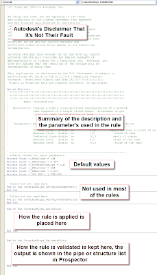
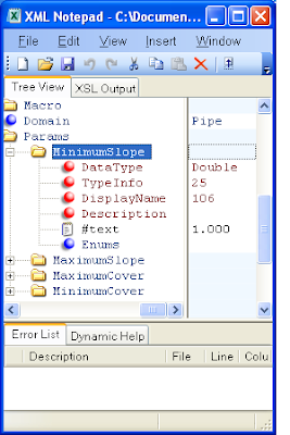
When you set up the XML file to tell Civil 3D what values to use, you probably want to have the user see the correct number format. Civil 3D uses a numeric code to determine what format the number should be. It is stored in the XML file under the TypeInfo under the Params folder. Type 25 is a percent number, Type 16 is feet or meters. Those are the two types used in the rules, I haven't tried to figure out what the other numbers do, so I can't provide what they do here.
Monday, November 19, 2007
Changing Drawing Units
http://fredbobchris.googlepages.com/ChangeUnits.html
If a little blue down arrow shows up after changing the values to the right of the unit changed, make sure to click the blue arrow to override the naughty children.
Thursday, November 15, 2007
Autodesk University - Supercalifragilisticexpialidocious Sewer Design
VBA Programing Examples:
Laterals
Pipe List w/ Formula
Pipe Network Quantity
Alignment Custom Rule (C3DPipeRules.dvb)
Alignment Custom Rule XML (C3DPiperules.xml)
Links:
http://www.civil3d.com/2007/07/using-pipe-sample-vba/
http://www.civil3d.com/2007/11/modifying-cover-and-slope-rule/
http://civil-3d.blogspot.com/2007/11/anatomy-of-rule.html
Other Point Description Code Samples:
Pipe Slope: oPipe.Slope
Alignment Name: oPipe.Alignment.Name
Pipe Length: oPipe.Length2D
Connected Structure Start: oPipe.StartStructure.Name
Connected Structure End: oPipe.EndStructure.Name
Pipe Description: oPipe.Description
Pipe Diameter: oPipe.InnerDiameterOrWidth
I put all of my pictures, PowerPoint and cad files on the internet. They may be found here:
http://fredbobchris.googlepages.com/CV304-3P.zip
http://fredbobchris.googlepages.com/CV304-3P-CadFiles-1.zip
http://fredbobchris.googlepages.com/CV304-3P-CadFiles-2.zip
http://fredbobchris.googlepages.com/CV304-3P-CadFiles-3.zip
The screencast of the presentation may be found on the AU website.
Monday, November 12, 2007
Changing Profile Vertical Curve From K to Length
http://fredbobchris.googlepages.com/ProfileKLength.html
Wednesday, November 07, 2007
Laydel Command
Here is the link:
http://fredbobchris.googlepages.com/LAYDEL.html
Saturday, November 03, 2007
Expression to Control Rotation of Label
 To create an expression for the label we need to use an If statement to see if the Station Offset Label is to the left or right of the alignment. Then based on what the value is we set the rotation to 90 or 270 degrees. Since the rotation value uses radians, and I don't do radians, we will need to convert the degrees to radians with the DEG2RAD() function.
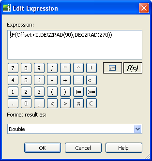 I placed an example that isn't pretty, but works on the Intermittent Block or Style of the Day site (see 11-03-07).
 Thursday, November 01, 2007
Did you know?
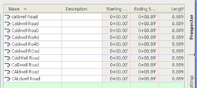
Just specify the title case you want when adding the Alignment Name to a label so they will all look like the same name.

Civil 3D Links
Autodesk Related:
http://www.civil3d.com/
http://acecivil3d.blogspot.com/
http://usa.autodesk.com/adsk/servlet/index?siteID=123112&id=3091031
http://discussion.autodesk.com/index2.jspa?categoryID=17
http://discussion.autodesk.com/forum.jspa?forumID=83
http://discussion.autodesk.com/forum.jspa?forumID=85
http://discussion.autodesk.com/forum.jspa?forumID=33
http://usa.autodesk.com/adsk/servlet/index?siteID=123112&id=3566722
http://labs.autodesk.com/
http://au.autodesk.com/
http://aec.cadalyst.com/aec/article/articleDetail.jsp?id=282051
http://civil-3d.blogspot.com/
http://civil-3d.blogspot.com/2007/07/command-reminders.html
http://civilcommunity.autodesk.com/
http://www.google.com/reader/view/# (My subscriptions XML file)
Other Links:
http://www.ccb.org/
http://www.pcase.com/
http://www.coastalreprographics.com/index.asp
http://www.dipra.org/
Sunday, October 28, 2007
Changing an Alignment's Stationing
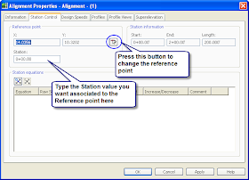
To change the station reference point, go to the Alignment Properties, Station Control Tab. Press the icon next to the Y: value of the Reference Point. When the message box pops us press OK. Then select the new reference point you want the stationing to emanate from. Then if you wish, change the station value to the one you want.
Sunday, October 21, 2007
New Data Shortcut Functionality in Civil 3D 2008
If you haven't moved from Civil 3D 2007 (SP3) to Civil 3D 2008 and you use data shortcuts here is another reason you may want to upgrade.
In Civil 3D 2007 (SP3) data shortcuts where located by object handle and name. In 2008 they changed how the xml file is created and now the data shortcut only cares about the object handle. This means that if you start out with Street A type names for the alignments you can change them to the actual street name once you get them.
As an added bonus the program makes the change when you bring the file forward from 2007 to 2008. So if you have this problem currently, now is a good time to upgrade.
Wednesday, October 17, 2007
Editing Dimension Annotation
I'm going with something that I just discovered with doing some CAD work. You can use the ddedit command to modify text in a dimension style. Just type ddedit and then select the annotation in a dimension label you want to modify. It even keeps the original dimension in the label, if you want or you can delete it and add your own fake dimension. Much easier than the way I was doing it through Properties.
Monday, September 17, 2007
Changing Sides/Attachment Point in Subassemblies

There is a way to change it by going into the subassembly properties dialog box (just right click and choose subassembly properties...). Just go the parameters tab and click on the side box and choose left or right.

You can also change the attachment points of curbs in this same manner.
And since it was overwhelming in the poll questions to add pictures, I did this time.
Tuesday, September 04, 2007
Profile Views
Create a profile view for the range of the profile you want shown as proposed. Next create a profile view for the existing station range. Now just set them side by side with the matching station adjacent to each other. The profiles should look like one profile. To change one of the profiles to look different go in to the Profile View Properties, Profile tab and set the Override Style to the one you want to show. You now should have a profile that changes looks along its range.
Sorry no pictures, just being lazy today.
Thursday, August 23, 2007
Line Table
This method needs improvement, but it does create a AutoCAD table of bearings and distances or any other information you want added.
- Map>Object Data>Define Object Data (add field for tag number)
- Map>Object Data>Attach/Detach Object Data
- Go to lines and assign number in properties window (for tag)
- Map>Tools>Export
- Save as ESRI SHP file.
- On the selection Tab choose line and the objects you want exported.
- On the Data tab add the information you want in your table.
- Save the profile for use the next time.
- Open the *.dbf that is created during export.
- Copy the cells you want for your table.
- Paste Special the cells into AutoCAD as AutoCAD Entity.
- Change the format of the angle cells to Surveyor's Units.
- Use the Annotation feature under Map to add the Tag labels.
You may need to fill the holes by using Help, you may even find a better way and not have to export the file while looking in Help.
Saturday, August 18, 2007
Autodesk University - 2007
Also I am looking to do a run through of my AU presentation here in San Luis Obispo, CA. I'm looking to do it on September 18. If you are interested then drop me a line at fredbobchris@gmail.com for additional details.
Friday, August 10, 2007
Watch Out for Elevation Data
Tuesday, August 07, 2007
AEC Modify - Divide
This also works on other objects than just blocks and may be an alternative method to break lines without having a gap. I can never remember how to break a line or polyline and not have a gap.
Sunday, July 29, 2007
AEC Modify - Subtract
It takes linework and trims out one linework from another. The two benefits of this command is that you can trim blocks with it and trim with AEC objects, such as subassemblies. To use just right click in model or paper space and choose AEC Modify Tools> Subtract select the linework you are going to subtract from (or edit) then press enter and then choose the objects that are going to subtract from the first objects selected.
Look on page 1395 of the User's Guide for a picture of how the command works.
The User's Guide is located at C:\Program Files\Autodesk Civil 3D 2008\Help\civil_ug.pdf
Friday, July 27, 2007
Posting Elsewhere
Below is a link to sample code which is similar to what I posted at Civil3d.com. The code at the link below gives the point at an offset of 10 feet from the assigned pipe's alignment.
http://fredbobchris.googlepages.com/intermittentblockoftheday
The code is in no way complete, but will provide a good starting point to create your own code for creating points from your pipes.
Thursday, July 26, 2007
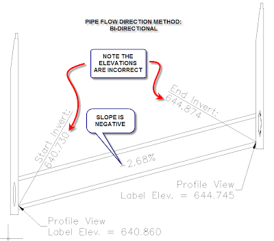
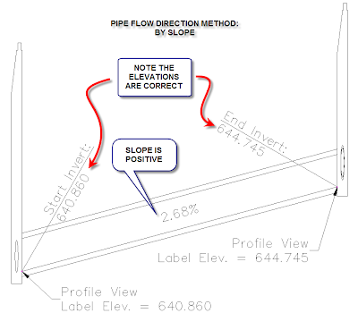
Pipes and Slopes
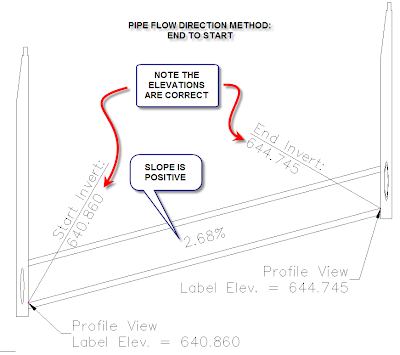
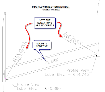
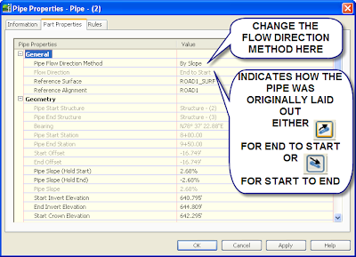
Tuesday, July 24, 2007
Command Reminders
LAYOUTREGENCTL
Set to 0 for regen each time
Set to 1 for cached view
Alt-0160 For a null character in a field (Gets rid of an error in a field that hasn't been set, ie the second line of a sheet title using the custom properties in Sheet Set Manager.)
INPUTHISTORYMODE
Changes from giving coordinates to original values typed into the command line. Don't know if it affects dynamic input. Use one of the lower values, set to 2.
filedia=1
cmddia=1
Use when the program changes these values to 0.
\X
To have a second line text in dimensions.
PSLTSCALE=1
LTSCALE=1
Just the settings the office prefers.
SCALELISTEDIT
MIRRTEXT
Changes the mirror to actually mirror text, or mirror text so the text is legible.
MAPWSPACE
Turns on and off the Map task pane.
convertpstyles
Converts the drawing from a ctb plot style to an stb plot style or the other way around.
Change all of the Blocks in a drawing to unitless:
(vl-load-com)(vlax-for x(vla-get-Blocks(vla-get-activedocument (vlax-get-acad-object)))(vlax-put-property x "Units" 0))
Copy and paste it into the command line and it will change all of the blocks to unitless. If the 0 is changed to 1 then the blocks are changed to inches, 2 is feet, 3 is miles, 4 is mm, 5 is cm, 6 is meters, 7 is km, 8 is microinches, 9 is mils, 10 is yards, 11 is Angstroms, 12 is nanometers, 13 is microns, 14 is decimeters, 15 is Dekameters, 16 is Hectometers, 17 is Gigameters, 18 is Astronomical Units, 19 is Light Years, 20 is Parsecs.
ATTSYNC - Update block attributes.
Reset User Profile and Settings: http://usa.autodesk.com/adsk/servlet/ps/dl/item?siteID=123112&id=14929107&linkID=9240697&CMP=OTC-RSSSUP01
Default Template Location: C:\Documents and Settings\Christopher.Fugitt\Local Settings\Application Data\Autodesk\C3D 2010\enu\Template
PLINETYPE Allows you to draw Polyline2D, change the values.
Friday, July 20, 2007
AEC Modify - Trim
This is helpful for trimming against Civil 3D objects that you can't trim to using the normal trim command. For instance if you have a line in profile view and you want it trimmed to a profile you can do it with this command. The only thing lacking in my opinion is the ability to select a profile vertical curve as an edge.
Tuesday, July 17, 2007
Extending Linework to an Edge
The AEC Modify Tool > Extend allows you to extend to an object, similar to the basic Autocad extend, except this one alows you to extend to a plane of the target edge. It's kind of hard to explain in word so the following pictures should show feature.
The original two lines, I am going to extend the blue line to the edge of the red line.

Choose the AEC Modify Tools>Extend
Select the lines you want extended, then press enter, then choose the edge to extend to:
 Select a point near the end you want extended:
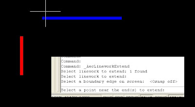 Result of the command:
This also works the same way as the regular extend command. Another benefit of using this is that if you select multiple lines to extend you only have to click once to get all of the them to extend to the edge. No using fence, selecting each one, etc...
Saturday, July 14, 2007
Sewer Lateral Code
For it to work it requires that all of the pipes involved have alignments assigned. See the pipe rules post for an easy way to assign an alignment as you layout a pipe network horizontally.
Once started you will be prompted to select a sewer lateral pipe. This will select the pipe and the program will use the pipe network the pipe is in. I separate the main line and sewer laterals into two pipe networks. This is so the laterals don't break the main line pipes when I am laying them out. Then select a main line pipe. It will then adjust any pipes in the sewer laterals pipe network that have an offset of +/- 1' from a main line alignment's pipe. It adjust it so the invert of the lateral pipe is at the top of the pipe. If you want to match another part of main line pipe, just adjust the code to put it where you want. The code is in two spots near the end of the code.
The code may take a while depending on how many pipes are in the network. This is mainly because I am not an expert programmer. The file can be found here, Laterals.dvb.
Thursday, July 12, 2007
Same Numbers for Parcel/Alignment Tags
Pipe Rules Fixed - I think???
http://fredbobchris.googlepages.com/intermittentblockoftheday
Let me know if I created any other problems: fredbobchris@gmail.com
Tuesday, July 10, 2007
Pipe Rules Blues
- For one if you are far away from zero, it may give you an overflow error. Just change the integer value to Double for all of the Dim, except i.
- If an start/end point doesn't project to the alignment it returns a value of zero instead of null.
I currently am looking for a solution to 2.
Sunday, July 08, 2007
Feeling Brave? Custome Pipe Rules
I've written two rules for Pipe Networks. So far I haven't had any problems, but who knows what the future holds. The two rules are called Alignment and AlignmentLaterals.
Alignment: This assigns the alignment to the pipe based on the start and end stations offset values. If the start offset and end offset are +/- 1 foot away from an alignment in the drawing the alignment is set as the reference alignment.
AlignmentLateral: This assigns the alignment to the pipe based on the start and end stations offset values. If the start offset or end offset are +/- 1 foot away from an alignment in the drawing the alignment is set as the reference alignment.
The files for download have been placed here. I've only tested this in 2008 and probably doesn't work on earlier versions The file location on your computer should be in a location similar to this:
C:\Documents and Settings\All Users\Application Data\Autodesk\C3D 2008\enu\
To use the new rules, copy the existing two files with the same name to a new location as a backup. Then place the two files you downloaded into the folder you found the original two files. Restart Civil 3D, if you had it open. When you open up Civil 3D the two new rules will be available when you create rule sets, or apply it to existing pipes.
I'm not the greatest programmer so the code is probably slower than it should be. I also don't know exactly happens when you share the file with someone else who doesn't have the custom rules. I'm pretty sure it is just an error message in the event viewer.
Let me know what you think.
Friday, July 06, 2007
VBA Program
http://fredbobchris.googlepages.com/intermittentblockoftheday
Wednesday, July 04, 2007
Custom Pipe Network Rules Part I
This is just a reminder to myself how to do the first step, adding the information to the xml file which will point to a rule in the C3DPipeRules.dvb file. I would not suggest doing this until I get more information or if you have an install that you can mess around with. I don't fully know the ramifications of this or if it actually works.
- Open the C:\Documents and Settings\All Users\Application Data\Autodesk\C3D 2008\enu\C3DPiperules.xml file. I prefer the XML Notepad.
- Expand the folder heirachy under Categories, then Category, then Tools.
- You should see a list of Tool under Tools.
- Copy any of the Tool Folders by right clicking and choosing copy.
- Paste the item under Tools.
- The first thing we need to do is give the idValue, under ItemID its own unique identifier. If I remember correctly it should be a random string of numbers, so change the numbers randomly. Hopefully I will find out where you can generate the idValues, until that time changing it should work.
- Next expand Properties, ItemName. The resource is how it chooses what name it uses in Civil 3D. Choose a alpha only name for the new rule, without quotes. If you put in a number such as 155, Civil 3D will give you an error message that it can't find resource 155 but will add the resource to the list of rules as 155. If you use quotes Civil 3D will also give you an error message. Leave the src alone.
- Next expand Data, Macro and type in a name of what you are going to call the module and routine in the VBA file. I'm going to call it SetSumpDepthCustom.SetSumpDepthCustom.
- Next expand the Params and rename SumpDepthValue to SumpDepthValue2
- Change the DisplayName under SumpDepthValue2 to Sump Depth Custom.
- Set the #text to 0.5
- Now save the XML file.
- Open Civl 3D and the rule will be listed in the list of rules, in this case for structures.
I haven't created the macro yet so an error message is appearing in the Panorama window stating that it can't find the macro. This is a good sign since it looks like you can create a custom pipe rule this way and have it apply to the network. The next step is creating the macro and getting that to work.
Saturday, June 30, 2007
Adding a VBA Macro To a Toolbar
- Type CUI at the command line.
- Press the new command button
- Create a new Toolbar
- Type in the following format of the vba macro to get it to load and run, notice that the folder separators go in the wrong direction: ^C^C-vbarun;"C:/Documents and Settings/user/My Documents/Autodesk/PipeNetworkQuantity-0.1.dvb!ExcelExportLengthCount.ExportToExcelLengthCount";
- Add an icon and drag the command from the lower left area up to the new toolbar
Thursday, June 28, 2007
Pipe Networks Style Overrides
Just put the check mark in the box and select the style you want it to be. In 2007 you need to have the style already created, in 2008 the ability to create or copy and edit a style from the command is there.
Wednesday, June 27, 2007
Mapcheck Report in 2008
I told my coworker I was going to post on something else, but I found this new feature too cool to pass up and solves the problem he was having exporting a mapcheck report for multiple parcels. This post is mainly borrowed from the tutorials document on the Autodesk website.
Exercise 3: Exporting Parcel Data
In this exercise, you will generate a mapcheck report for the parcels in the residential road at the top right of the drawing.
In AutoCAD Civil 3D you can export inverse or mapcheck reports for either a single parcel, a series of parcels, or all parcels in a site.
For more information, see the AutoCAD Civil 3D Help topic Exporting a Parcel Inverse or Mapcheck Report.
To export parcel data
On the Toolspace Prospector tab, expand Sites ➤ Site 1 ➤ Parcels.
In the list view below the Prospector tree, click the heading of the Number column to sort the parcels by number.
- Select parcels that you need a report for. You can use any of the standard windows methods to select and deselect the parcels.
In the list view, right-click and select Export Analysis.
- In the Export Parcel Analysis dialog box, specify the following settings:
- Destination File: Place it in a place and with a name you can remember the tutorial uses a txt file like this: ExportAnalysis.txt
- Analysis Type: Mapcheck Analysis
- Destination File: Place it in a place and with a name you can remember the tutorial uses a txt file like this: ExportAnalysis.txt
- Click OK.
The ExportAnalysis.txt file automatically opens in the text editor associated with AutoCAD Civil 3D and is saved in the location you specified in step 5.
No more copying and pasting for each parcel or exporting into another program to get the reports, unless of course you need it in another format.
Tuesday, June 26, 2007
Sewer Lateral Layout
- First create a dynamic block or use the one found here.
- Add the label to a line and curve label, I have created a sample at the same location in step 1.
- Add the label at the locations along the alignment where you want the laterals to go.
- Flip any labels to the other side of the line or have two styles on for left and one for right.
- Make any adjustments you need to make.
- Explode the line and curve labels twice.
- If you are using Civil 3D you will need to save, close and reopen the drawing. Civil 3D 2007 crashes when you try to move a grip of the dynamic block. Civil 3D 2008 tends to like this a little more.
- Move the grips to the property line or whatever location the lateral needs to go to.
There may be other unforeseen problems, but should save step in rotating each sewer lateral block.
Monday, June 25, 2007
Combining Pipe Networks
When you do this make sure the pipes and structures have different names or change them after you do the import. Having pipes or structures of the same name will cause problems in the drawing.
Saturday, June 23, 2007
DWG Version Converter
For Civil 3D files you will need to make sure Proxygraphics is set to 1 before sending out for them to see something other than empty rectangles. Also the labels don't rotate to match the paperspace viewport, only rotate per Model Space.
Evan Almighty
First the whole dam portion of the plot was ridiculous and totally out of whack with reality. For one a dam is in no way governed by building codes as mentioned more than once in the movie. Dams, at least in the State of California, are governed by the Water Resources, Division of Safety of Dams or the Army Corps of Engineers. While the supporting structures are governed by the building codes, the dam is in no way contained in the building code.
The premise of a Congressman being able to control the building process enough to have a dam of the size shown built shabbily is also ridiculous considering the amount of people involved in the construction of a dam. First you have the agency who needs the dam for drinking water storage or for Storm flow storage. Since most agencies no longer keep a large number of staff on hand an engineering company is hired to design the structure, then you have a Contractor who is going to build the dam. Then you have all of the people who are against dams, regardless of the benefits, that would point out any and all perceived design flaw. Each participant has some liability in the final output (except for the anti-dam people), I could concede that one participant could do the faulty construction, I do not think a Congressmen could pull this off, let alone profit from it. While Civil Engineers are not specifically singled out, the film does shed Civil Engineers in a bad light since it is guilt by association.
My next beef with the film is the impression that development is inherently bad because it occupies land previously undeveloped. All I have to ask is where are these people supposed to live? All these people are are children and immigrants (both legal and illegal). The only way to stop the destruction of natural places is to stop the production of people. I don't think that is a realistic solution to the problem. Another solution is infill in existing cities and towns. Unfortunately this also has problems, since a portion of people are adamantly against this. For instance any development project in the award winning downtown in the city San Luis Obispo, where I work, is derided as not fitting in and potentially destroying the character of downtown. How can this be, since this is how the downtown was created in the first place. The downtown of San Luis Obispo was created by various building dating from the mid 1700 to current day. People are also against building up, at least a portion of people in my town, so it looks like the current proposal to increase the height of buildings may not go through. An increased height would potentially increase the density of downtown and prevent the development of agricultural or raw land.
Quite frankly I am tired of going to movies and being preached at on environmental issues. It is especially galling that the movie cost $175 million dollars to make. If they really wanted to make a difference they would have saved 20% ($35,000,000) of the cost of the movie, bought the land they profess should be saved, and prominently provide an advertisement of where people could add to the fund (either at the beginning or end of the movie or both). But I guess they really don't believe it and are only trying to sell tickets.
Tuesday, June 19, 2007
One Vertical Curve for Sag and Crest
To have one style for sag and crest vertical curves with and without high and low points. So you can just have on main label style for sag and crests.
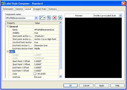
- Add a line to the label. Set the Start point anchor component to the Anchor Curve High Point and the End Point Anchor to the Midpoint of the Dimension Line. Give the line a name so you can remember what it does.
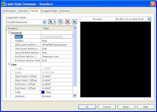
- Next create a line construction line which will be hidden in the style, but will help rotate the text parallel to the dimension line. It is needed because we have to tie to the previous line created and have a way to make it look like the other text in the label. If you skip this line then it will be nearly impossible to get the rotation right as the label is moved up and down.
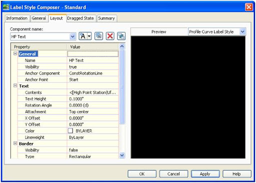
- Next add the text to the label for the HP. Use the anchor point of the start of the construction line you created in the last step. Add whatever text you require for the HP.
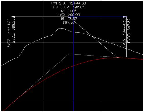
- Here is a picture of how the label looks.
- Just change the visibility of the HPtoMidDimensionLine and the ConstRotationLine to false so it not seen in the final style.
- Repeat the steps for the low point, using different names for the components.
- Since the low point and high point portions of the label are anchored to the low or high point the those portions of the label won't show if there isn't a high or low point of the curve.
I have also uploaded the HP portion of the label here.
Friday, June 15, 2007
Sheet Set Manager
Tuesday, June 12, 2007
Profile and Profile View Labels
Monday, June 11, 2007
Working Between Civil 3D 2007 & 2008
Autodesk University
I went last year and had a fun time.
Sunday, June 10, 2007
Google Analytics
Its really eye opening to see where Civil 3D users are that visit the site, or visit it accidentally. So far a total of 21 countries are represented:
United States - Canada - Costa Rica - Peru - Spain - Bosnia and Herzegovina - Italy - Serbia and Montenegro - Germany - Belgium - Netherlands - United Kingdom - Romania - India - Iran - Malaysia - Isreal - South Korea - Australia - New Zealand - Kenya
Most of the viewers are from the United States though, with 25 states and the District of Columbia represented, mostly from California though.
Most of the users where refered by caddigest.com
Thursday, June 07, 2007
XML Notepad
It makes it alot easier to see and change values in the XML file.
Tuesday, June 05, 2007
Taskbar

One session of Civil 3D, two files open with Taskbar setting of 1:
 The first one is the default and to switch between drawings use alt+tab, for the second one switch between drawings with alt+tab.
The option to change it in Microsoft Office products is under options. This is from Microsoft Office 2007.
 The change in the UI for the Microsoft Office is a bigger change the CTRL click for subentities in AutoCAD.
Increase Command Line History
http://discussion.autodesk.com/thread.jspa?messageID=4145019
ConvertLineworkToMaskBlock
 A box will pop up. I usually choose the Select AEC Objects to Mask option and let the computer name the Mask Block. I also check the Erase layout geometry so it deletes the original polyline. After you hit OK you will be asked to select which objects you want masked, in this case I am masking a profile.
Before:
 After:
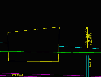
I masked the top profile.
Make sure you place the Mask Block on a non plot layer so it doesn’t show up. To add or remove objects just select the Mask Block right click and the option is there. You can also edit the shape using the edit profile in place option in the right click.


