Sunday, August 31, 2008

Isolating Objects

Ever since the base AutoCAD program changed the way layers are isolated, I have found I have been using the Isolating Objects command that comes with Civil 3D more often. This command is great since you can isolate objects just by selecting them.

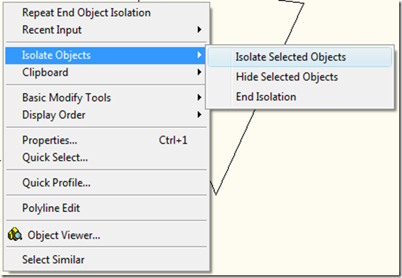
To use the command select an object and go the right click menu. Choose the right-click, and click Isolate Objects Hide Selected Objects.

image

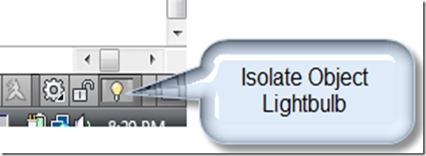
Now just the objects you selected are shown. You can also get to the command from the Tray at the bottom of the screen with the light bulb icon.

image

Yellow indicates no objects are being isolated and red indicates objects are being isolated.

To end the isolation just use the End Isolation option by right clicking on the light bulb and the objects will reappear.

Friday, August 29, 2008

HEC-RAS Report 2

Well in the last post I covered how to fix an error, but lets say you want to show more or less significant digits. To do this type VBALOAD and find the vba file for the HEC-RAS Tools. Do a search for Round in the entire project. You should find some lines of code that look similar to this:


ReachCoords(q) = Round(oStation.Easting, 2)


The Round() function takes a number, in this case the easting of an alignment PI point, and rounds it to the corresponding digits. For this line of code the number format would be 5.12, which is probably good enough. But lets say the boss wants to see it to four digits, well just change the 2 to a 4 and the output will now be four digits.


There is a problem using the Round() function in VBA. The problem is that it uses banker's rounding so instead of rounding in the normal manner you were probably taught in school, the number is rounded to the nearest even number if a 5 is the digit for rounding. So 1.235 and 1.245 will both give the result of 1.24 instead of 1.24 and 1.25 respectively.


To get normal rounding you can use the Format$() function that will round normally. It just converts the number to a string, but in this case it should be acceptable. The code could be revised to be:


ReachCoords(q) = VBA.Format$(oStation.Easting, "#.00"))

You could also look at the vba code reports and change the report to look at the drawing settings to get the rounding value or put the number of digits to round to in the form used to run the report so you can change it when you run the report.

Thursday, August 28, 2008

HEC-RAS Report

If you haven't heard, Autodesk released a revised HEC-RAS tool to import and export data between Civil 3D and HEC-RAS. It is available to download from the subscription site.
It appears that some of the code doesn't work correctly if you have free curve in the alignment and then reverse the alignment. The error message that is recieved is the one below (run-time error Invalid input.).

I'm not sure if the error is in the report or in Civil 3D. It appears that the entity count of the alignment returns a larger value than what is in the alignment. In my case I had three entities, but it returned that I had six. So when it ran looking for six, Civil 3D indicates that it isn't there and you get the error message. To fix it press the debug button and replace the code in the Public Function GetStreamCoords to End Function with the code below. This code uses a different method to get the PVI stations, the one from the original HEC-RAS report that shipped with the program. You may want to make a backup copy of the report in case it doesn't work.

' Get the stream alignment coordinates

' Fills up the stream network end points section

Public Function GetStreamCoords(ByRef ReachCoords() As Double, calign As AeccAlignment, csurf As AeccSurface)

Dim PLSta As Double

Dim PLOffset As Double

'Station & Offset of Pline Beg. Pt.

Set ReachEnts = calign.Entities

ReDim ReachCoords(0 To (ReachEnts.count * 4 + 3))

Dim oStation As AeccAlignmentStation

Dim q As Integer

q = 0

For Each oStation In calign.GetStations(aeccGeometryPoint, 0#, 0#)

ReachCoords(q) = Round(oStation.Easting, 2)

ReachCoords(q + 1) = Round(oStation.Northing, 2)

ReachCoords(q + 2) = Round(csurf.FindElevationAtXY(ReachCoords(q), ReachCoords(q + 1)), 2)

ReachCoords(q + 3) = Round(oStation.Station, 2)

q = q + 4

Next

End Function

Tuesday, August 26, 2008

Autodesk University 2008

Well it looks like my main reason for not going to AU 2008 (AU2009 moving to June) may or may not be a possibility. I guess Las Vegas is popular in June and commands more money. So I'll let you the readers decide if I should ask the bosses if I may go. Just vote in the poll to the right of the page. I'll do what ever the poll results come out as, I just can't promise that the bosses will let me go.

Toolbox (2008) VBA Reports - Nothing Happens

If you ever have one of the dvb type reports not be able to run and doesn't post an error message to the Event Viewer you may need to run a repair on Civil 3D 2008 to get the reports to work correctly.

From what I can tell the dvb program is erroring out after it checks to make sure Civil 3D is running and that is triggering an error message. The next error catcher in the program exits the macro without sending an error message to the Event Viewer, which makes it appear that nothing happened.

Sunday, August 24, 2008

Right Click Menus

I'm a keyboard user of Civil3D and don't always look for the right click options. With grip editing I knew you could hit the space bar and go through the various options (stretch, move, rotate, scale, mirror, move or rotate) but I didn't realize you could right click and get the same list of items to choose from. This may come in handy if you want to use stretch, but accidentally hit the space bar, since stretch doesn't come up again. Most of the other commands with options in the command line have the same right click feature.

image

Wednesday, August 20, 2008

Corrugated HDPE Part Catalog

Thanks to Engineered Efficiency I am able to provide a Corrugated HDPE Part Family. The part family is based on the Hancor Drainage Handbook and includes sizes from 4" to 60". The part family can be downloaded using this link.

To get the pipes to be included in your catalog, unzip them and place the files in the following folder:
Vista: C:\ProgramData\Autodesk\C3D 2009\enu\Pipes Catalog\US Imperial Pipes\Circular Pipes
or
XP: C:\Documents and Settings\All Users\Application Data\Autodesk\C3D 2009\enu\Pipes Catalog\US Imperial Pipes\Circular Pipes\

The AeccSharedPropertyLists.xml file isn't part of the catalog, but lets you add HDPE as a material type.

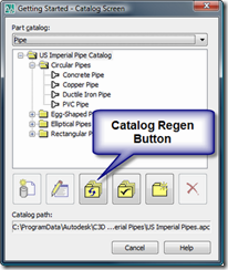
Once copied over, go to the Pipes menu, Part Builder and click on the catalog regen button. The corrugated pipe should then be available to add to a parts list, although it may not show up after clicking the button. If it doesn't show up click the folder with check mark button and try again.

RegenButton

If you have any questions regarding this, just send me an email at Christopher@Civil3DReminders.com or add a comment.

Sunday, August 03, 2008

AECPOLYGON Revisited

AECPOLYGON's not just for architects anymore.

What is an AECPOLYGON? An AECPOLYGON is a polyline with a hatch associated with it. No while that sounds like a regular hatch it is so much more. This post will summarize the how to create them and then how to modify them.

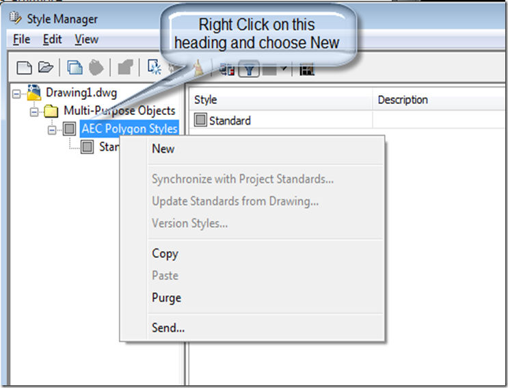
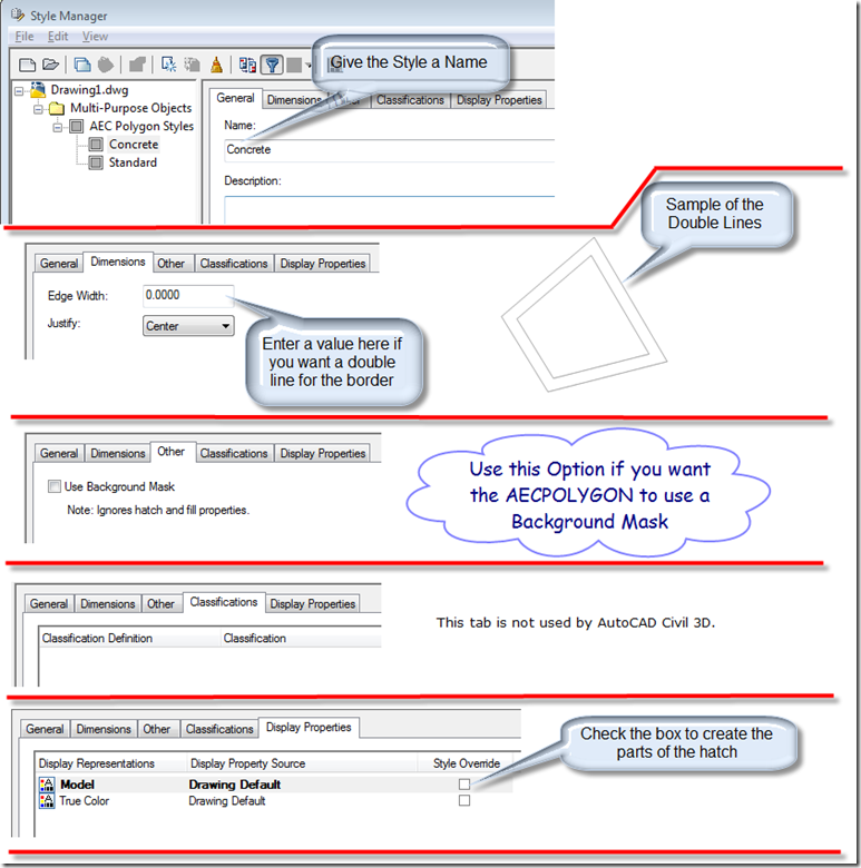
The first thing you are going to want to do is create some AECPOLYGON styles. To create the styles type AECPOLYGON at the command line and choose the Style option. When the Style Manager comes up (yes, there is a style manager in Civil 3D, it just doesn't handle Civil 3D styles) right click on the AEC Polygon Styles and choose new to create a new style.

image

Now go through the tabs at the top of the style to set the settings of the new AECPOLYGON style. The picture below summarizes all of the tabs.

image

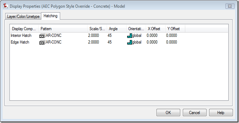
When the Style Override box is checked the Display Properties dialog box will pop. This dialog lets you set what type of hatch you are going to use and what portions of the AECPOLYGON should show or be hidden. The Hatching tab shown below lets you set the pattern, hatch scale, hatch angle, orientation and X Offset, Y Offset. The orientation is either global or object. The X Offset, Y Offset adjusts the hatch start point. So if you have a block wall hatch you can have the hatch start at half a block.

image

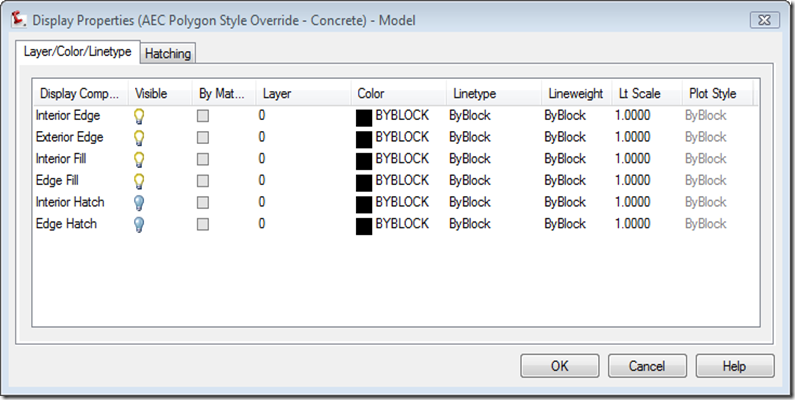
The Layer/Color/Linetype tab lets you assign layers to the various portions of the AECPOLYGON and determine if it is on or off.

image

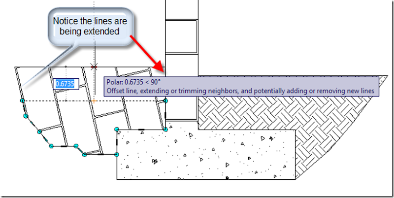
After you have create some styles you are ready to create some AECPOLYGONs. There are two ways to create them. The first is by using the Add option. The Add option lets you draw the AECPOLYGON. The Convert option lets you take a polyline and make it an AECPOLYGON. If you use the Add option you can set the style by pressing the Style option or change it in the properties window. If you forget to change the style you can always change it in the properties window. After you create the AECPOLYGONs there are various ways to modify them. The easiest way to modify them is to select them and use the grips. The grips have some benefits over regular polylines since they have a middle grip that acts like a line grip and adjusts the connected vertices of the AECPOLYGON.

image

As an added feature using the Ctrl key cycles through several modifications you can do to a vertex or edge. The picture below shows the various options.

image

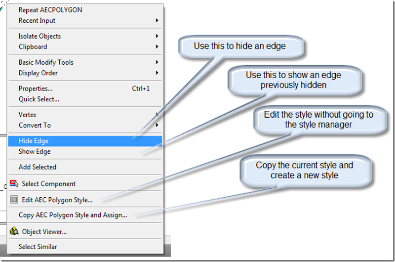
So looking at the above detail you may be thinking that you don't want the earth to have line at the portions below the surface. Well you can hide those edges and keep the top surface. To do this select the AECPOLYGON and right click and choose the Hide Edge option. Notice all of the other options you can choose.

image

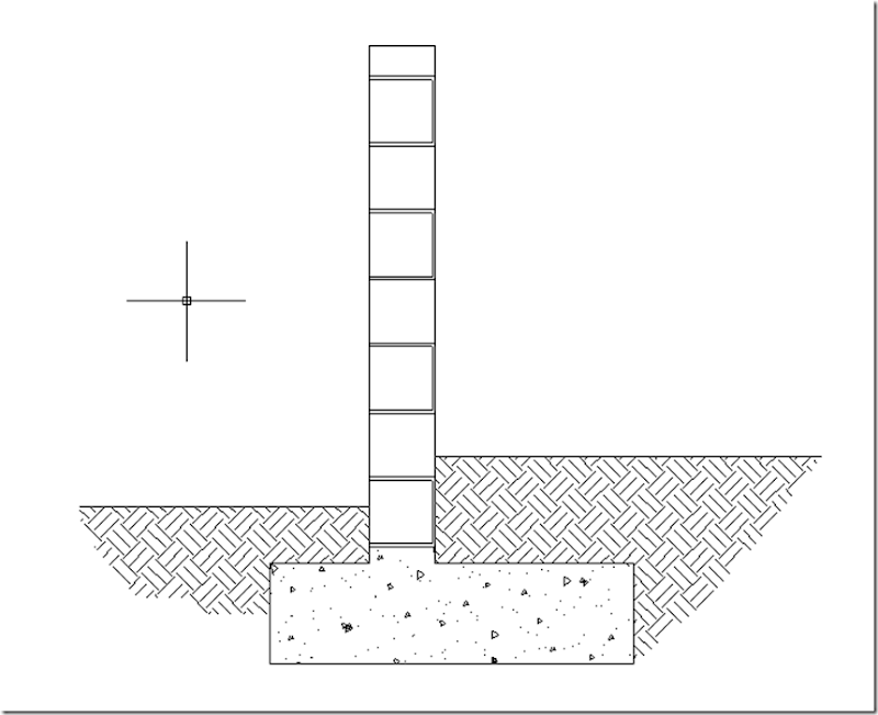
Below is a partially completed detail using only AECPOLYGONs.

image

So now that you have some styles you probably want to add them to other drawings. To do this open the style manager. Go to the menu bar and choose open. From there you can open other drawings to move styles between the drawings, just drag and drop them between the drawings.

Hopefully you can see the benefits of using AECPOLYGONs. To get you on your way this drawing contains the styles used to create the detail above.