Tuesday, December 30, 2008

Vertical Curve - HP/LP Split Profile Vertical Curve Label Style

OK, I messed up on the previous version of this post. The text was huge instead of small and I didn't realize it since I didn't zoom extents and if the low/high point was the BVC or EVC the label still showed it at the correct size. But have no fear I know another way to do it, it requires a knowledge of vertical curve equations and the use of expressions.

The first equation we have to use is the R equation, which results in the the % grade change per length.

R = (G2-G1) / L

Where G1 is the grade in, G2 is the grade out and L is the length of curve. The expression would look like the one below. The *100 is because the formula works as a % value instead of the decimal.

(({Grade Out}-{Grade In})*100)/{Profile Curve Length}

So now that we know the rate of change of the vertical curve we can calculate the Turning Point which is the high or low point of the grades used for the vertical curve. The Turning Point is measured from the starting curve station and may be positive or negative or extend past the end of the vertical curve end point which is important to know later on. The formula for Turning Point is:

-G2/R

The expression in Civil 3D is:

-({Grade In}*100)/R

So know we now know where the HP or LP occurs for the vertical curve we can create the expression that checks to see if the HP/LP occurs for the vertical curve. The expression is below:

High Point

IF({Grade In}>=0,IF(TurningPoint>0,IF((TurningPoint+{Profile Curve Start Station})<{Profile Curve End Station},.1/12,0.0000000000000000001),0.0000000000000000001),0.0000000000000000001)

Low Point

IF({Grade In}<=0,IF(TurningPoint>0,IF((TurningPoint+{Profile Curve Start Station})<{Profile Curve End Station},.1/12,0.0000000000000000001),0.0000000000000000001),0.0000000000000000001)

The expression first checks to see what type of curve this could be based on the positive or negative incoming slope. Next the expression checks to see if the turning point is positive. If it's negative the turning point is outside the vertical curve. Finally the expression checks to see if the turning point + start station extends past the profile curve end. If all of the items are true the text height is set to 0.1/12 and if any of the IF statements are false the text height is really small using the 0.0000000000000000001 number.

So that fixes the label. The corrected drawing may be found in the link below. Sorry for the mix up, but I guess the saying is true, you get what you pay for and I don't get paid enough for doing these posts to pay for a QA/QC process. The drawing uses both the R expression and Turning Point, but they could be combined into one. I wouldn't suggest adding it the other label since doing so makes the expressions really long for the determining expression.

The DWF below shows the HP label, and the DWG file may be found on this page.


Top 10 Posts For the Year

This year I've done 127 posts, including this one. The table below shows the top 10 posts visited this year (well one was a search result page).

NumberPostVisits
1Vertical Curve Across Profile1247
2Pipe Network From Profile950
3Create a Profile without a Surface - VBA766
4Point Transformation726
5Sample Lines VBA642
6Pipe Network Search564
7Labeling A Point on A Parabolic Vertical Curve536
8Drawing Conversion Scale - Example449
9Autodesk University - Supercalifragilisticexpialidocious Sewer Design429
10Question: VBA Structure Table408

To recognize the top post visited being a vertical curve style, my next post will be another post regarding vertical curve labels.

Sunday, December 28, 2008

World Viewers

Well the year is almost over and I understand lots of people go on vacation between Christmas and the start of the New Year. Instead of doing useful posts for the rest of the year I'm going to post on stuff that's probably only of interest to me. In this post I'm giving you a table of the top 10 countries of where the readers of this blog come from. The entire list is 145 countries, but I suspect a lot of them showed up by accident because they came only once or twice (27 countries total).

United States

14,054

Canada

1,950

United Kingdom

868

Australia

516

India

385

Italy

296

Germany

283

Netherlands

262

Brazil

250

New Zealand

237

Thursday, December 25, 2008

US Viewers

This is the second post in a series of uninteresting posts. In this post I'm providing a table of the top 10 States in the US of where the readers of this blog come from. The entire list contains all 52 states. Manchester, New Hampshire had a total of 144 visits (89 coming from an Autodesk Network, so at least on Civil 3D developer occasionally reads the blog).

California

2,640

Texas

1,216

Washington

803

Florida

795

Colorado

546

New York

467

Virginia

442

Pennsylvania

404

Arizona

391

Illinois

379

Monday, December 22, 2008

Miracle or Something Else

The current media coverage of the accident of Continental Flight 1404 is focusing on the statement of Assistant Denver Fire Chief Bill Davis' statement of "It was a miracle...that everybody survived the impact and fire." While all of the facts on how the accident occurred will not be known for quite a while while the NTSB investigates the incident, I think he, and the media, needs to give credit to the individuals that ensured that fatalities would be limited. How about mentioning the work Engineers did in designing safety features into the plane, or the flight attendants who instructed the passengers on how to exit the plane in an emergency and then hopefully assisting the passengers in exiting the plane in a safe manner. Or the firefighters who arrived and extinguished the fire in a quick manner, or the developers of the fire suppression system that enabled the fire to be extinguished in about 45 seconds. It seems to me the media focuses too much on sensationalist statements or on what went wrong rather than what goes right.

Sunday, December 21, 2008

Congratulations Alexander

I'd like to congratulate my brother, Alexander, on officially becoming an Eagle Scout. I attended his Eagle Court of Honor yesterday to see him get the official recognition of the achievement which he completed EagleScout_4Ksome time ago. This wasn't my first Eagle Court of Honor I've attended, I attended my own in '92 and my other brother's in '94 along with numerous other individuals from Troop 675 in Irvine California, but this one definitely had the most Eagle Scouts sitting in the Eagle's Nest. There was 25 Eagle Scouts, including the three who where being recognized in attendance. Usually it's about five other Eagle Scouts.

I've always appreciated the achievement of becoming an Eagle Scout but don't think I recognized the magnitude of the achievement until yesterday.  I knew about 4% of scouts that join the Boy Scouts became Eagle Scouts and understood what it took to become an Eagle Scout, but I think Mike Rowe's letter (from Dirty Jobs fame) put the achievement in a different perspective for me. I think it shows how difficult achieving the award is and how it takes perseverance to follow through with it.

Tuesday, December 16, 2008

Skipping the Feature Line Dialog Box

So you have lots of polylines to convert into feature lines and you don't want to see the dialog box that pops up each time, what to do? You could shoot your monitor, but you'd probably get fired. Here's a more productive method using VBA. The code below is pretty basic, it doesn't have any fancy bells and whistles though. The first part of the code has you pick the polyline you want converted. If you wanted to do 3Dpolylines, just change the AcadLWPolyline to Acad3DPolyline or you could have the code accept both types of objects, that's for another post or a chapter in a book.

Once we've got the polyline we need to make sure a site exists to put the feature line in and if one doesn't exist the code goes ahead and creates a new site called "NewSite". Now the code creates a variable to store the feature line objects in which is part of the site. The site used is the first one in the Sites list. If you wanted to get fancy you could add a prompt for the user to have the ability to select a site, but that's another post. Next the first feature line style in the drawing is used for the feature line style. Now finally the feature line is created.

image

The code above may be found on this page: http://style.civil3dreminders.com/programming

Monday, December 15, 2008

Disneyland

Disneyland has announced it is giving a special day for Civil DDD at Disneyland, see the link below.
http://www.sun7news.com/index.php?firstname=Civil&lastname=3DDD&celebration=Holidays

Well not really, if you want your special day or someone else you know. Take the link above and change the Civil to your first name and the 3DDD to your last name.

Yes, I'm a sucker for giving people free advertising.

How to Create Civil 3D Points for Each TIN Vertex - VBA

The From the Ground Up Blog had a post on how to create COGO points from a surface. The post may be found at this link: http://civilcommunity.autodesk.com/blogs/blog/6/blogpost/10511/

While the method works it could be easier using some programming. The first thing we need to do is make sure we get the Civil 3D document so we can add the points to the drawing.

image

Next lets have the user select the surface they want the points created from. The On Resume Next is error catching in case the user doesn't select an object or escapes out of the command.

image

So now that we have the object we need to make sure it is a surface. Once we make sure the object selected is a surface we need to create the points. To do this we will get the points out of the surface using the Points Method of the surface. The Points is a list (an array) of points in the X,Y,Z format. Next we'll create the Civil 3D points using the AddMultiple method of the Points Object. To use the AddMultiple method we need to give how many points we want created, the list of point locations (an array) in X,Y,Z format and what number to start with in the array. The code below shows the completed code.

image

The above code creates points without a description, so additional work would be needed to add the descriptions. The method should be easier than exploding the surface. The completed code may be found on this page: http://style.civil3dreminders.com/programming

Correction Post: http://blog.civil3dreminders.com/2008/12/how-to-create-civil-3d-points-for-each.html

Wednesday, December 10, 2008

Create Points with Elevation

I was surprised to find when you create a Civil 3D point the manual way it doesn't keep the elevation of the place you select. I guess I've never noticed. Well here's a way to get the program to keep the elevation.

First thing that needs to get done is to get the base Civil 3D objects. I just copied the code from the sample programs that come with Civil 3D.

image 

So now that we have the base Civil 3D objects we can create the rest of the program. First thing that needs to be done is to create a variable that is the Points Object of the drawing. Once we have that we can create a point and add it to the collection, but first we need to prompt the user to select a point. To do this I'll use the GetPoint utility.

image

So that's the basic code to get it to work. As with all my free stuff it needs some error catching, maybe a On Error Resume Next (not the best method), or adding a description to the point or a point number. Maybe in another post. To save you some time, I've posted the code here.

Wednesday, December 03, 2008

Action Recorder

I was pretty disappointed when the Action Recorder first came out. I was hoping for a product more like the macro recorder in the Office products that writes the actions in VBA. I do find the action recorder useful in seeing if you can program the creation of Civil 3D labels by sending the required information to the command line. For instance you can create a General Label by sending the AddNoteLabel to the command line and then send the location where you want the label to be placed (X,Y format).

The AddNoteLabel will use the default style set in the command settings. To change it using VBA use the following line of code:

g_oDocument.Settings.GeneralCommandsSettings.AddNoteLabelSettings.StyleSettings.NoteLabelStyle.Value = "Standard"

Where the "Standard" is the name of the style you want to use and the g_oDocument is the global variable that is used in the sample vba projects that ship with Civil 3D.

Autodesk University Not Even Unplugged

Took a detour from my vacation to go golfing with the EE golf outing on Monday and the AU Blogger's Social on Tuesday. I had a good time in the warm weather of Las Vegas golfing with Matt Kolberg and Dave Dixon. My golf game was horrible as usual, but Dave and Matt are decent golfers. At the AU Blogger's Social got to meet some fellow bloggers as well as some of the Autodesk marketing people. The marketing people where nice enough to arrange to get me a pass to go through the exhibit hall.

Before going to the exhibit hall I was able to sneak into the last part of the Civil 3D Beta Launch. I did sign a non-disclosure form so I can't divulge what I saw, but the features did look like it would be worth upgrading from Civil 3D 2008, the version I'm using at work, to 2010 when it comes out sometime next year. If you want to beta test it you can sign up for it at the myfeedback.autodesk.com website.

The exhibit hall had lots of exhibitors showing their products, but it seemed there was less giveaways this year. I only ended up with one t-shirt, a pack of gum and Playdoh from the Engineered Efficiency booth. The Engineered Efficiency booth had Rock Band set up and seemed to be popular with people standing around watching the action. I got to meet some of my coworkers from around the country. It was also interesting to get recognized this year by people. At the two previous AU's I attended I was more under the radar.

My short visit to AU is done for this year and now I'm headed onto Utah to enjoy the scenery.

Monday, December 01, 2008

SynchronizeReferences

Sometimes at the computer at work the notification of data shortcuts being out of date doesn't work. Without the notification it can be time consuming to update the data shortcuts one at a time. To force an update off all of the data shortcuts in the drawing the SynchronizeReferences command can be used. The command updates all of the data shortcuts in the drawing.

Tuesday, November 04, 2008

Pipe Rules - Making the Pipe BySlope

When laying out pipes you can choose the slope method with the slope button to make the pipe's flow direction to go from Start To End or End To Start, you don't have the option to have it use the By Slope flow direction. You can set up a custom pipe rule to accomplish this task and that is what I am covering in this post. I'm not going to cover all of the steps, for the steps I don't cover you can get from my AU 2007 paper or from previous posts regarding pipe rules.

To start you will need to decide, at least for Civil 3D 2009, to choose what programming language to work in. I'm going to use VBA, though you can use vb.net to accomplish the same task. This first step is to open the C3DPipeRules.dvb file using VBAMan and then do a SaveAs of the file. I'm going to call the file C3DCustomPipeRules.dvb. Next I'm going to rename the PipeLength module to PipeBySlope.

image

Next go to the edit menu and choose Replace. Replace all of the instances of PipeLength to PipeBySlope. This will rename all of the macros to match the name of the Module. Next move the highlighted text to the location indicated below.

image

Next add code to make the to set the flow direction of the pipe. The highlighted code below.

image

Next delete the code in the validate section. The code should be as shown below.

image

Next delete the Modules that aren't needed.

image

Next modify the C3DPiperules.xml file to add the pipe rule to Civil 3D and your done.

image

Monday, November 03, 2008

Parcel Segment Description

I was working on some VBA stuff and stumbled across that Parcel Segments have a description value. I checked the parcel labels and didn't see an option for adding a description to the label. Thinking that couldn't be correct I went to a different label that had a description label component and copied it and pasted it into the parcel line label. The text for the Description is <[Description(CP)]> and it showed up in the label. The label preview won't show the value, but it does show up in the added label.

I think of some uses for this such as adding other bearing and distance information to the parcel segment without editing text of the actual label. I would think selecting the parcel segment and typing the information in the Description spot in the Properties window would be easier than editing all of the labels.

image

I haven't actually tested how robust the modification is, but I did open and close the drawing and the change persisted.

In the upper right corner of the page is a link to a Sheet Set Manager Program that will renumber the sheets in a sheet set or help manage the total number of sheets in a sheet set with Custom Sheet Set Property with a push of a button. While not free, it is rather inexpensive.

Wednesday, October 29, 2008

Expressions - Radians

This is it my 200th post and a reminder to myself that when using angle values in expressions they are in radians. A complete circle is 2pi. A half a circle is pi.

An example how this can used may be found in this link. http://style.civil3dreminders.com/checkrightorleft

This example uses expressions to indicate if the curve at the PI goes to the right or the left.

Tuesday, October 28, 2008

Civil 3D User Group Meeting in SLO

There is going to be another SLO Civil 3D user group meeting on November 12. This link has the information: http://fredbobchris.googlepages.com/SLO-Nov122008.pdf

If you do attend, I'm going to attempt to give away my signed copy of Mastering AutoCAD Civil 3D 2008 again. If you see me and I'm holding the book just ask for it and its yours. I've got to make space for my 2009 version of the book.

Monday, October 27, 2008

Elevation Analysis - VBA Style

One of the items you can't seem to store in your template is how the Elevation analysis is applied to a surface. If you find yourself always changing the values to a default, this post may help you become more productive.

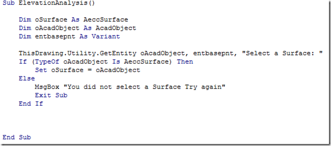
The first thing we need to do is select a surface. This is how I did it:

image

Once we have a surface then you can create the elevation analysis regions you want to the surface. This routine assumes that one has not been applied yet. If you already have created one, you may want to remove the existing one first or modify it.

image

In the sample above the code is creating 2 regions. If you want more just change the value. Once the regions are created we can change the properties of them. We do this by creating a new SurfaceElevation object. Next we have to set the values that we want to use for the regions. Here is the code to do it.

image 

Follow the pattern and do the same for additional regions. Like most of the examples on this site, no error catching has been added, such as On Error Resume Next line to get rid of an error message if the user didn't select an object. Have fun.

Wednesday, October 22, 2008

HEC-RAS Extension - Bonus Feature

Autodesk has provided the HEC-RAS export report for subscription members, now get the Civil3D Reminders Bonus Feature for the extension. Sure you have to do most of the work yourself, but you don't need to fork over money to get it (unless you want too, I won't say no).

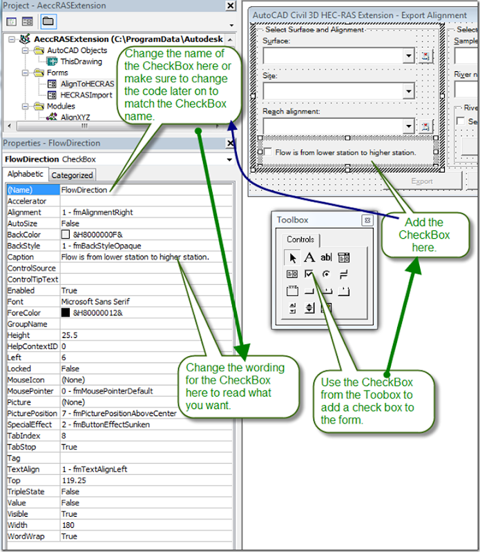
In the current report you only get to have the flow direction of the stream go one direction, from a lower station to a higher station value. With the Civil 3D Bonus Feature you get to choose if you want the stream to go the opposite direction. The first step is to add a CheckBox to the AlignToHECRAS form. To open the form double click it in the Project list on the left side of the screen. Then use the Toolbox to add a CheckBox, it fits conveniently below Reach Alignment box. Change the name of the CheckBox in the properties area under (Name) and enter a caption that indicates that the flow direction of the stream will be reversed if the CheckBox is checked.

image

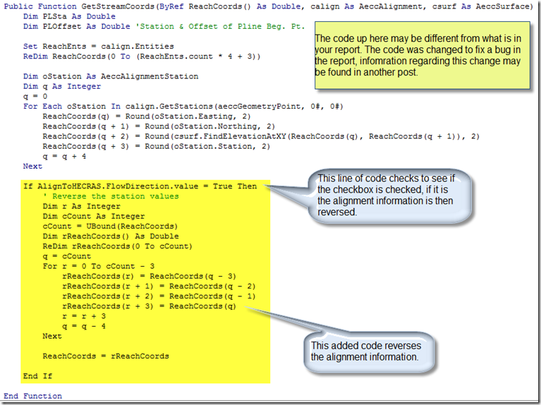
Now that we have created the CheckBox we can modify the code to reverse the information that is written to the report. HEC-RAS determines the flow based on how stream is drawn. It assumes the first point is upstream and the rest are downstream from it. The code below reverses the information, moving the first point to the back and the last point to the front.

image

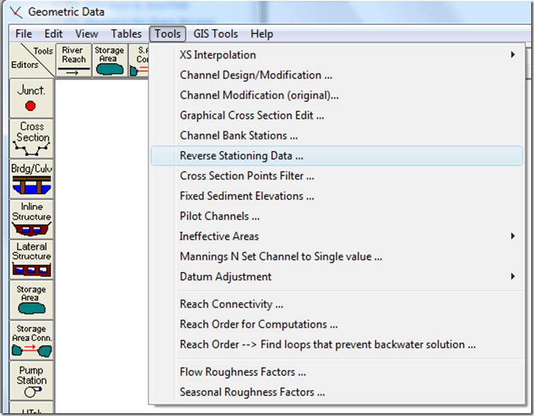
Once the code is finished you are ready to run the report. Once imported you will want to check the data, in accordance to the HEC-RAS user manual, especially to see if the sections are drawn correctly. If they are not use the Reverse Stationing tool to reverse the cross section. HEC-RAS assumes the cross sections are entered from left to right looking downstream. If after using the tool the cross sections are backwards, let me know and I'll see about modifying the code to get them to come in correctly.

image

Here are the results of running the revised code with the CheckBox checked and unchecked from HEC-RAS:

image image

Sunday, October 19, 2008

Tc Inquiry - VBA

One of the tasks engineers have to do is Tc calculations. While Civil 3D lets you use label the overall length of a feature line/3DPolyline it does not let you have access to the start and end point elevation of the line. If access was allowed to the start and end point elevations you could use an expression to do the Tc calculations. This post covers how you can calculate the Tc using VBA. The code adds a text label with the Tc value.

The first thing we need to do is to have the user select a 3DPolyline. The code to do this is shown in the picture below.

image

Now that we have the 3DPolyline we can process it to get the required information from it.

image

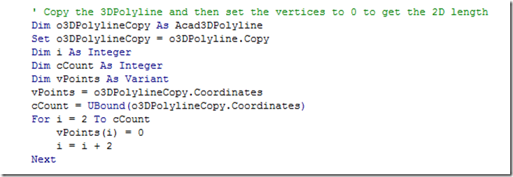
As shown above getting the ending a starting points is rather easy. The vertices information for a 3DPolyline is contained in the Coordinates part of the object, which is an array type object that starts at 0. The starting elevation is the second value since 0 corresponds to the X value of the first vertex, 1 corresponds to the Y value of the first vertex and 2 corresponds to the Z value of the first vertex. To the the last vertex information we need to determine the number last value in the array. The Ubound() provides that information by giving the number of the last value in the array. The length value of the 3DPolyline is the actual length of the 3DPolyline. Since most methods of Tc was created before widespread use computers the length needed is the 2D length of the line. To get this we need to make a copy of the 3DPolyline and then set all of the Z values in the coordinates array to 0. There may be a better way to do this, but this is the way I thought to do it. If you think you should use the 3D length you skip adding the code below.

image

The code takes all of the vertices and adds it to an array then sets the Z values of the vertices to 0. If you can follow patterns you should recognize that every third value is the Z value for a vertex. So that is why at the For i = 2 part of the code it starts at 2 and then process every third value. The Next adds 1 and the i = i +2 has the code move every third value.

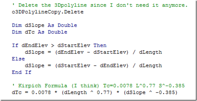
So now that we have modified the vertices we need to set the vertices of the copied 3DPolyline to the modified values. The change is done below and the length is gotten and then the copied 3DPolyline is deleted.

image

Now we need to calculate the slope, but before we do that we need to make sure we get a positive slope (unless you have water that goes up hill). The if then statement does this in the code below. The Tc value is then calculated.

image

The Tc formula may not be the one you use, or you may have to use different constants contained in the 0.0078 value. So make sure the Tc formula is the one you have to use.

So now that we have a Tc value lets add it to a text label and place it where the user selected the 3DPolyline. The code to do that is below.

image

The text height is hard coded in the above example, so if you want it to be something else go ahead and change it.

This example assumes you use the waterdrop feature in Civil 3D to generate the line so you can ensure that the 3Dpolyline slopes from a high point to a low point. If you use an alternative method to create the 3DPolyline you may want to add a check to make sure the 3DPolyline slopes in one direction (such as drawing a polyline and then using the surface drape tool). You can also add the other information used in the calculations to the label or export the information to an Excel spreadsheet.

A copy of the completed code may be found on this page of the style site.

Tuesday, October 14, 2008

Giveaway Conclusion

Cathy gave the correct answer to the Giveaway. The correct answer was Branch Street in Arroyo Grande, CA.

Cathy has declined the prize, so know I have to figure out what to do with the box of stuff, autographed copy of Mastering Civil 3D 2008 and a bag of Belly Flops.

Thanks to all that participated.

Monday, October 13, 2008

Change the State Storage Extension to Acre-Feet

Brian requested in the last post regarding the Stage Storage Extension to have the report be changed to Acre-Feet instead of cubic feet. The easy way to do this is to employ the same strategy as the last post and do a find of cft and replace it with AF (or what ever other abbreviation you want). Next we'll have to change the math to include the conversion from cft to acre-feet. Use the Find, choosing the Current Project search option again, to look for:

An1 = CA(1, i)

Once you find it you should be in the module for UserForm2, ProcessPlines macro. It should look like the picture below.

image

Go ahead and make the changes as shown below, make sure you like the conversion rate.

image

If you don't mind your newly created acre-feet values rounded to the nearest whole number you can quit and move on with your life. If you want it rounded to a different value you'll have to do another step. Scroll down a bit from the changed code above to what is what is shown below:

image

This code formats the values into a whole number. Make the change below to have the numbers formatted to two digits.

image

If you want a different format, go ahead and change it. The formats shown in Excel tend to be the same as what is used for this VBA function.

The changes to the code for this extension are just quick fixes to get the results you want. Ideally the code would be revised to let the user select the units or pull the unit settings Civil 3D.

Friday, October 10, 2008

Changing the Stage Storage Extension to Meters

The Stage Storage Extension provided to subscription users uses feet and cubic feet as the units it shows. Since the program just does basic arithmetic and doesn't change the units it is fairly easy to change it over to metric.

The first step is to load the report using vbaload from the command line. The vba program is located at:

C:\ProgramData\Autodesk\C3D 2009\enu\Data\Reports\vba\SST.dvb (at least in Vista)

Next we need to look for all of the instance of ft or feet and change them to m or meter. To do this go to Edit menu and choose Replace. In the dialog enter in the find what box ft and in the replace box m. Press the find next button to find all of the instance of ft to replace with m. Make sure you use the Replace and Find Next buttons to select the instances that show up in the report. Next do the same, only using feet and meter instead. Now all of the output should be in the correct units.

Next we need to modify the dialog boxes. To do this expand the forms folder as shown in the picture below and double click on the UserForm1 and then change the Contour Area to the correct units.

image

image

This is the quick and easy way to do it. If you wanted you could have it read the units from the drawing and automatically use the correct units, but that's a little more complicated than what can fit in this post.

Wednesday, October 08, 2008

Isn't that the Point?

Read an article that lawmakers were angry after they learned that AIG execs went on a retreat after the Government provided $85 billion dollars to prevent the company from collapsing. Sure the company shouldn't waste money, but they also need to spend money to help Main Street. Congress telling financial companies that they shouldn't spend money is counterproductive. Maybe I'm mistaken, but I never thought of flight attendants, masseuses, porters, gate attendants, desk help, housekeepers, groundskeepers, etc. as rich. This money went to support the existence of their jobs. If financial companies don't spend money on retreats then all you are doing is hurting the people that rely on this discretionary spending, further hurting the economy. They had these events before the financial turmoil they should have them afterwards to support the people who provide those services. Discouraging this type of expenditures also hurts the Civil Engineering profession through less tax revenue for transportation projects (airports and roads). Way to go Congress for looking out for the little guy again.

Tuesday, October 07, 2008

Two Excel Windows

If you double click on an Excel file while a current Window of Excel is running it will open in the current running version of Excel instead of opening a new Window. I like having to have two distinct Windows of Excel running. To do this go to start and open a new instance of Excel (or use a desktop icon).

Monday, October 06, 2008

Surface Boundary

Did you know you can use parcels objects as a boundary? I didn't so I decided to play around with it. I found adding parcels objects didn't quite work as I expected. You can only select one parcel object, which I find a great limitation. When you select a parcel label the boundaries of the parcel are highlighted. I would expect the ability to select the parcel label and have the boundary of the parcel added as a boundary or when you select multiple parcel objects, have the computer see if they made a closed shape and add the resulting closed area as a boundary.

You can also use a polygon as a surface boundary, though I haven't quite figured out what that means. The help just mentions polygon without indicating what type of object they are referring to and the Developer's Guide gives an example of a circle. I did try using AECPOLYGONs and MPOLYGONs as a surface boundary and both didn't work. I used the polygon command, but that just creates a polyline.

Another thing abound surface boundaries I learned is that the parcels objects, polygon or polyline doesn't need to be closed. The program will automatically close the boundary by connecting the beginning and ending points of the added boundary.

Thursday, October 02, 2008

Jelly Belly

The Giveaway is still on. Even if you don't know the answer you could still win. Just email christopher@Civil3DReminders.com. In addition to the box of stuff and autographed copy of Mastering Civil 3D 2008 I'm throwing in a 2# bag of Belly Flops. Belly Flops are just like Jelly Belly Beans, just didn't make the cut in the size department (either too big or too small). They don't tend to last long in the free candy dispenser at work.

When ever I'm in Fairfield, CA I try to stop at the factory and take the tour. You get free samples and see how they make the candy.

Tuesday, September 30, 2008

Vertical Subassembly

Due to an overwhelming response to the Giveaway, I'm adding a signed copy of Mastering AutoCAD Civil 3D 2008 to the box.

Now to the last post of the month. If you use the vertical subassembly you may notice that it has a slight offset to the right. This is because a TIN surface cannot have a vertical face. The offset works great if it is added to the right side of the assembly, but it can cause problems if it has been added to the left side. To correct it you can download Microsoft Visual Studio Express (vb.net version) and then change then change the code and then rebuild the project. Since most people don't have Microsoft Visual Studio I'm going to modify the VBA version of the subassembly.

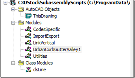
The first step is to load the C:\ProgramData\Autodesk\C3D 2009\enu\C3DStockSubassemblyScripts.dvb (this is the Vista path, you'll have to find the XP path if that's the system you are using) using the VBAMAN command. Then press the SaveAs button to make a copy of it. Then press the Visual Basic Editor button to bring up the Microsoft Visual Basic editor. I like clearing out the stuff I don't need, so I deleted the modules I don't need. The list of Modules that you need are shown in the picture below.

image 

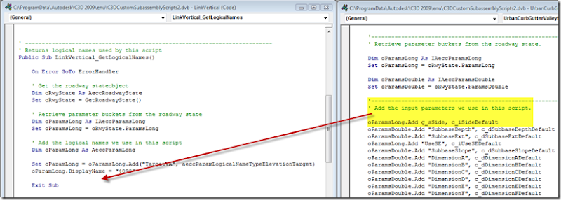
You don't really need the UrbanCurbGutterValley1 (Urban), but I'm going to use the side code from it. So double click on the UrbanCurbGutterValley1 to get the window to pop up. Also do the same for the LinkVertical (Link) Module. Then copy some lines of code from the Urban to the Link as shown below:

image

 image

This line of code gets the side input we'll add to the subassembly.

image

This line of code flips the .002 based if it is right or left. For the right side it stays positive and for the left side it changes to negative. This line of code is applied when the subassembly is shown in the assembly.image

This does the same as above, but it applies when the corridor is being built.

image

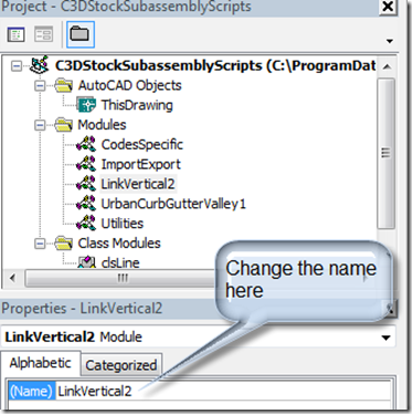
So now we have changed all of the code we need to change. So before we're done lets change the name of the module. I'm going to change it to LinkVertical2.

image

Also change all of the instance of LinkVertical to LinkVertical2. To do this press ctrl+H and type in LinkVertical in the top box and LinkVertical2 in the bottom box. Then press Replace all. Press the save button. Also change the C3DStockSubassemblyScripts to the name of the dvb file.

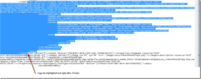
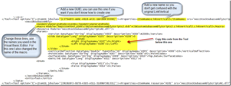
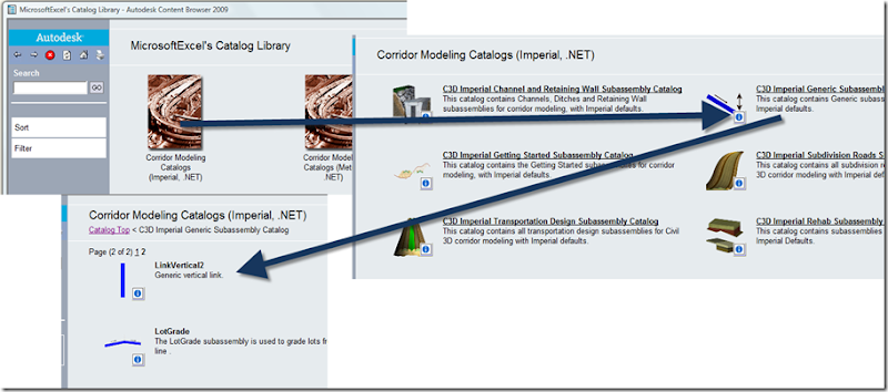
Next open the C:\ProgramData\Autodesk\C3D 2009\enu\Tool Catalogs\Road Catalog\C3D Imperial Generic Subassembly Catalog.atc file in Notepad. Copy the vertical link tool text as shown below:

image

Next make the revisions shown below to the copied code:

image

Save the file and then go into the Catalog and find the LinkVertical2. Drag it to the Tool Palette using the iDrop. Then use the subassembly in the normal manner.

image

I posted the revised subassembly on this page: http://style.civil3dreminders.com/customsubassemblies

You can make similar adjustments to the other subassemblies using this method. You may get quicker results if you modify the vb.net code, but that's another post.

Monday, September 29, 2008

Confidence

Confidence in the financial markets makes my job possible. A developer takes a piece of raw or previously developed land and adds value. The developer takes money from investors or banks (essentially taking on debt) to build the project. The developer, if not the original landowner, has a contract with the current landowner to purchase the property once the entitlement process is done or purchases the property outright. If the developer decides not to build the project he/she takes a loss on the development. If you take a look at the builder losses it is mostly due to writing off these costs of land in the development process. This is hopefully a short term problem. The developer takes the loss and once the market hits the bottom the developer starts the process over again. The problem comes when the builder can't win the confidence of the investors and banks to fund the process.

Today I think that banks are not willing to fund this and based on the vote of the House of Representatives vote today, I can't blame them. The Government is being given the chance to buy debt for $0.20 on the dollar. Since most of the debt is mortgages the Government is essentially telling us, the American people, that we don't have confidence in you to repay this debt. Sure some of the debt will go in default, but I don't think that 80% of the mortgages will default. 

I think we have to remember why this debt is being priced so low. It is because investors are unwilling to purchase it. Think back to high school economics and you should remember that when demand goes down, the price usually goes down. So essentially the financial markets are in a downward spiral. A bank can't effectively price the debt because it is hard to value how much they can get for the debt. If one bank sells the debt at a low price, the other banks have to reprice the debt on their own debt. Once the debt is marked down the bank has to have more assets to keep it's balance sheet within the limits set by the Government. If the company is unable to raise new capital it is declared insolvent and taken over by the Government. A recent example of this is the takeover of Washington Mutual. The Government got lucky, as well as us the taxpayers, in that they where able to get another bank to take over the bank without it being liquidated by the Government. A portion of Washington Mutual's problem was depositors removing their deposits (losing confidence in the bank), making raising capital even more important.

Today the Government had the chance to say they had confidence in the American people to pay back the debt and provide liquidity to the market to provide new loans. I'm not saying that it would immediately restore confidence, but it sure would have helped save some banks from closing. We'll see if Congress goes on breaks and lets the financial system hit bottom, or stay in session and try to create a floor above the bottom to save the American people from more hurt in the parts of the country that have been hurt the most. For instance if you live in Riverside County, an area especially hit by this downturn, you want a bank willing to loan to someone to live in the empty foreclosed home next to yours.

Hopefully this is just a small bump in the process and the users of Civil 3D who are out of work because of the downturn can get back to work helping to build the infrastructure needed to house and transport the people of America for today and tomorrow.

Sunday, September 28, 2008

Giveaway

I was working on my kitchen remodel today and didn't have much time to think up something for a post today. So instead of coming up with something regarding Civil 3D, I have decided to have a giveaway. I thought about giving away two tickets to Game 2 of the ALDS series between the Angels of Anaheim and the Red Sox, but then remembered I don't make that much revenue from this site. So then I looked around and saw that I had a bunch of parts I don't need anymore. So I'm giving away the random box of stuff. To win this stuff just tell me the town and street the testimonial portion of the commercial was filmed on. Just email me the answer, the first email I receive with the correct answer wins. Even if you have no idea, send me an email and if no one comes up with the correct answer by October 10, 2008 I'll have my daughter randomly pick a name out of a hat to pick the winner.

As for the two tickets to the ALDS I would be open taking a trade for the tickets, let me know what you got and I'll let you know if I'm interested. The tickets are in section F135.

e-mail: Christopher@Civil3DReminders.com

Saturday, September 27, 2008

Parades

The kids go to be in their first parade. It went for about a mile and they got to ride in their wagon. The path of the parade went past the place where the world famous Sham Wow commercial was filmed. It took me a few times watching the commercial to figure out that it was filmed in my home town. I think I was even at the event when they did the customer testimonials.

I took a hacksaw to the washer that was giving me trouble and now the sink fits in the whole.

Friday, September 26, 2008

So Close but So Far

Easy right. Just connect the faucet to the sink and then put the sink in the hole. Get the sink up and in the hole and find the washer that holds the faucet in place is blocking the sink from sitting properly. Hey maybe if I loosen the nut I'll be able to move the washer over and get it to fit. No luck there. Wishing I had a grinder to take off a part of the washer. Maybe tomorrow I'll figure out how to get it to fit. Dang manufacturer doesn't have customer service until Monday. Maybe I'll have better luck with exhaust vent tomorrow.

Thursday, September 25, 2008

Adding Boundary Again

I can't believe I did it again. Alright once more. When adding a boundary to a surface the name of the boundary cannot be the same as another one. It may have the same spelling, but the capitalization of the word needs to be different. Hopefully this time it sticks, if not it's going to be easy to fill out the rest of the month with posts;)

Adding Boundary

Sometimes I forget things and that's what this site is for. Today I'm hoping blogging about it will help me remember.

Surface boundary names needs to be DIFFERENT when added to a surface. I know it, but I make the same mistake over and over and over again. So when I choose to add more than one outer boundary I need to change the names. Remember, remember, remember & remember. I think everytime I make this mistake I'm going to do a post about it. Hopefully that will cure me of making this mistake over and over again.


And Blogger's online editor sucks at handling pictures. Cal Poly football is going to Wisconsin to play football this year. I hope they can turn the lemon into lemonade. Go Law??
Captions in Word

Well in this post I'm going to follow the lead of the the September AU Quarterly Newsletter, AEC Tech Tips Section and leave Civil 3D out.

If you have a large work document, such as a report, you may want to reference a table, figure or appendix in the document. If you use a the numbering tool or regular text you'll have to manually update the numbers if they change. Word provides a way to do automatically update, so if you add a figure any references in the

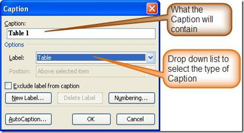
First you need to add the captions for the Table. To do this go to Insert on the menu bar and choose Reference > Caption.

untitled

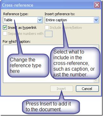
To reference the Table Caption go to the menu bar and choose Insert > Reference > Cross-Reference

untitled2

You can also add above/below to the reference to indicate where in the document the table or other reference is located at.

Wednesday, September 24, 2008

Ketchup or Catsup?

24 days, 25 posts only 6 more to go after this one. It doesn't look like I'll be going to AU, but I will be doing the best part of AU and going to the Annual Duffer’s open put on by the EE folks. I'll also see if I can sneak into the Autodesk University 2008 Blogger Social.

For this post I'll address the top search query from yesterday. The query was "civil 3d load vba routine". The easy way to load a VBA routine is to type vbaload at the command line. To run the routine you can type vbarun and choose the macro from the list. You can also load a VBA routine from the VBA Manager. To get to the VBA Manager type vbaman at the command line. You can also create a toolbar and load the vba routine from it. One way to do it is shown in this post.

Tuesday, September 23, 2008

Create a Profile Without A Surface - 3DPolyline VBA III

Continuing on the previous posts in this topic, this time I'll add selecting a profile and then adding the 3DPolyline information onto the profile.

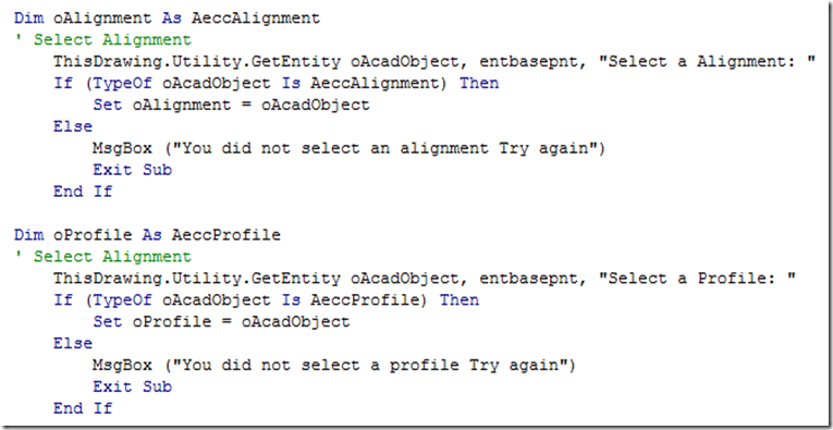
To select the profile copy the select alignment code and paste it below the select alignment code. Change the code to reflect the profile information.

image

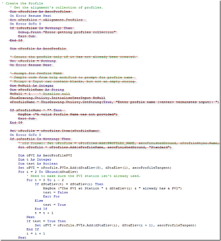
No go down and edit the code that previously created the profile. Delete the lines crossed out below.

image Also delete the End If statement under the oProfile.Update line under Next as shown in the above screen capture. This will get the job done, but some error catching needs to be done. Like you'd want to make sure the alignment corresponds to the profile or give a prompt to see if the user wanted to keep the old PVI or replace an existing PVI elevation if it happened to be the same. Another good feature would be to check to make sure the 3DPolyline projects to the alignment.

Related Posts:
Create a Profile without a Surface - VBA
Create a Profile Without A Surface - 3DPolyline VBA
Create a Profile Without A Surface - 3DPolyline VBA II
Create a Profile Without A Surface - 3DPolyline VBA III

Monday, September 22, 2008

Create a Profile Without A Surface - 3DPolyline VBA II

In the first post I demonstrated one way to convert a 3DPolyline to a profile. In this post will show how to have the user provide a name for the profile. Help provides various samples on how to get an input for a string. So I'll use the sample and modify it to prompt for a profile name. Put the new code above the Set oProfile = oProfiles.Item("FromPoints") line of code.

' Prompt for Profile Name
' Sample code from help modified to prompt for profile name
' Prompt & Input can contain blanks, but not an empty string
Dim NoNull As Integer
Dim sProfileName As String
NoNull = 1 ' Disallow null
ThisDrawing.Utility.InitializeUserInput NoNull
sProfileName = ThisDrawing.Utility.GetString(True, "Enter profile name (<enter> terminates input): ")

The NoNull =1 ensures that the user provides an input. If a profile name is not entered, the profile will be "", which is not a valid profile name. The True after GetString indicates that spaces are allowed. If it is changed to False, then spaces are not allowed. If enter is used for the profile name we will need to exit the sub in order to not get an error message for the user. So after the above code add the following lines of code:

If sProfileName = "" Then

MsgBox("A valid profile name was not given")
Exit Sub
End If

Now where ever "FromPoints" was in the code change it to the profile name variable sProfileName. No run the code and you should be prompted for the 3DPolyline, then an Alignment and then the Profile name. You could change the code to use a default value, but that's another post.

Related Posts:
Create a Profile without a Surface - VBA
Create a Profile Without A Surface - 3DPolyline VBA
Create a Profile Without A Surface - 3DPolyline VBA II
Create a Profile Without A Surface - 3DPolyline VBA III

Sunday, September 21, 2008

Year of a Million Dreams

Well it looks like the Year of a Million Dreams is no longer going on at Disneyland. I did want to get the chance to stay in the Dream Suite or take a tour of the Imagineering offices, but it doesn't look like it's going to happen. I did take a tour of the Dream Suite earlier this year and it looked like it would be a great experience for those lucky families that won. The dream suite had special features in the various rooms, like a model train that went around the top of one of the kids room and the toys became animated as the train went past. I guess eating at Club 33 will still be my favorite Disneyland memory.

Saturday, September 20, 2008

Back Side of Water

I'm not sure if the back side of water joke ever gets old, at least it didn't when me and my daughter went on the Jungle Cruise ride three times in a row.

This tip is for figuring out when is the best time to visit Disneyland. I think the blackout dates for the Annual Passes are a good indicator of when not to go. The annual passes are set up to allow the pass holder to visit Disneyland on various days, but other days are blacked out and the pass can't be used on those days. Disneyland has four pass types currently and range from 195 blackout days to no blackout days. I think when you can use the Southern California Select pass that would be a good day to visit Disneyland. The crowds shouldn't be that big and getting on the less popular rides is easier. For instance the wait for the Jungle Cruise was about five minutes today, I've seen the line take over an hour. The short wait time provided the opportunity to go on the Jungle Cruise three times in a row in under an hour.

Another tip when visiting Disneyland is to get there early. Not only are the lines shorter, sometimes the rides are longer. For instance the Carousel ride seemed to last forever early in the day. Later in the day the Carousel ride was noticeably shorter. If your going to stay the whole day save the popular rides to the end. Usually the lines are a lot shorter and you'll get the opportunity to go on more rides instead of sitting in multiple hour long lines.

Friday, September 19, 2008

Using Hidden Label Components

I posted a vertical curve style on the Intermittent Block or Style of the Day page which demonstrates you can create an extension line that doesn't go all the way from the PVI to the end and start of the vertical curve with a label. The person I was helping out was trying to use an expression to do it, while on the surface that sounds good, once you change the vertical scale of the profile view it doesn't work. A better way to achieve this is to use a hidden component. A hidden component will let you get the angle from the PVI to the start or end of the vertical curve. Since the rotation of components attached to another component uses a rotated UCS based on the orientation of the source component you can get the required angle (I'm not sure that made sense).

If you don't have 2009 installed you won't be able to download it and view how the label was created. So here are the general steps using the principal above.
  1. Add a line component anchored to both the Anchor PVI (Start Point) and the Anchor Curve Start (End Point).
  2. Set the visibility of the line added to false.
  3. Add another line and anchor the start point of the line to the end of the first line added.
  4. Set the distance of the line in inches (or mm) for the distance you want the gap from the curve start.
  5. Set the visibility of this line also to false.
  6. Add another line and this time anchor the start point to the PVI and the end point to the second line added.
  7. Add it to a vertical curve and you should end up with half of the label done and you can check to make sure the distances are like you want.

So to create the one line you have to have a total of three lines, two hidden and one showing. Now that I've completed 19 straight days of posts, I'm going to Disneyland.

Thursday, September 18, 2008

Civil 3D Content Browser

Coming home from a meeting and thought I'd open up Civil 3D and hit the help key to look for a topic to post on. The item that caught my attention was the Civil 3D Content Browser. While I knew about the content browser I never went further to see what other benefits it could have, other than containing the standard tool palettes that come with Civil 3D.

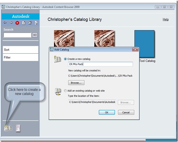
The main thing I noticed was the ability share Tools, Tool Palettes and Tool Packages from a website or network connection. The items that can be stored in them appear to be subassemblies, assemblies and utilities. So to try it out I'll created a list of Tools that I'll call the CR Pro Pack.

To open the content browser go up to the General menu or type ContentBrowser at the command line. To create a new Tool Catalog click the button in the bottom left corner of the content browser.

image

Now that it's created it has a plain cover page, which just won't do. So pick a picture, or create one, and right click on the catalog and choose properties. When it comes click on the image box and choose the picture you ant to show.

image

Now I want to create a new category to split out items. Press the CR Pro Pack catalog and you should get a blank screen. Right click in the blank area and choose the Add Category... option and give it a name you like. In this case I'm going to use Sample Code.

Press on the Sample Code to view the blank Category. To add tools to the category drag it from the Tool Palette to the Catalog.

image

You can add additional commands to the Catalog. You can then publish the Catalog to another location. To do this right click on the Catalog and choose Publish the Catalog.

image

You can use one of the three options, for this post I'm using the Copy it to another location.

image

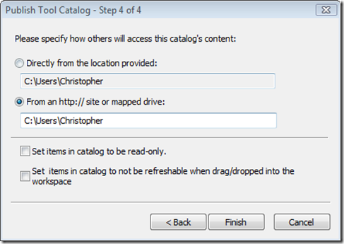
In step 4 of 4 you can set where others can access the Catalog such as a network location or mapped drive.

image

You can then share the Catalog with others by having them add the Catalog to their Library then adding it to the Tool Palettes.

image

There's lots more you can do with this, but I haven't figured them out yet.