Ad

Thursday, July 29, 2010

One Vertical Curve for Sag and Crest

I’m quickly approaching 500 posts. Instead of creating new and different posts I’d thought I’d recycle some posts leading up to the 500th post. (Hey! TV shows do it all the time.)

Here’s an older post showing how to have one vertical curve for both sag and crest. Unfortunately as posted originally it didn’t account for profile views that went from left to right. In order to fix it change the instances of Midpoint of the Dimension Line to <Feature>, Anchor PVI Dimension. Do this for all instances of the label components such as the Curve Data, HP and LP. The labels will then show correctly when the profile view direction is changed. If you’ve been moving your template by a save as from version to version you may want to go in and update the styles to utilize the additional <Feature> Anchor Point options which have been added. Especially if you have multiple vertical and curve styles to show the same information. The new anchor points provide the ability to remove some of the excess styles.

To have one style for sag and crest vertical curves with and without high and low points. So you can just have on main label style for sag and crests.

  • Add a line to the label. Set the Start point anchor component to the Anchor Curve High Point and the End Point Anchor to the Midpoint of the Dimension Line. Give the line a name so you can remember what it does.


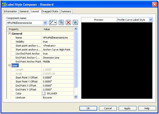
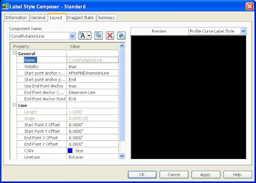
  • Next create a line construction line which will be hidden in the style, but will help rotate the text parallel to the dimension line. It is needed because we have to tie to the previous line created and have a way to make it look like the other text in the label. If you skip this line then it will be nearly impossible to get the rotation right as the label is moved up and down.


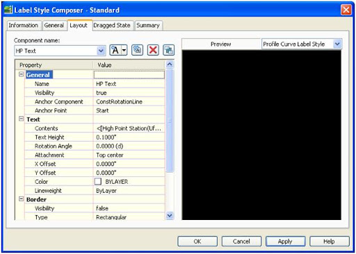
  • Next add the text to the label for the HP. Use the anchor point of the start of the construction line you created in the last step. Add whatever text you require for the HP.


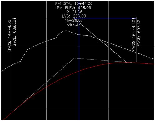
  • Here is a picture of how the label looks.


  • Just change the visibility of the HPtoMidDimensionLine and the ConstRotationLine to false so it not seen in the final style.
  • Repeat the steps for the low point, using different names for the components.
  • Since the low point and high point portions of the label are anchored to the low or high point the those portions of the label won't show if there isn't a high or low point of the curve.

    I have also uploaded the HP portion of the label here.

Here’s an updated example (Civil 3D 2010) based on James’ file in a post on Civil3D.com.

Tuesday, July 27, 2010

Slope Arrow Direction, Source: Autodesk University

I’m quickly approaching 500 posts. Instead of creating new and different posts I’d thought I’d recycle some posts leading up to the 500th post. (Hey! TV shows do it all the time.)

Autodesk University is coming up soon. Here’s one of the tips I discovered when I went. It provided a foundation for a bunch of posts I’ve done since the original publishing of this post.

A coworker was looking for a method to have a slope arrow always point down hill. He saw the method at AU, but couldn't find the handout which had it. I found the method on the AUGI web site. Since I will probably need this in the future, and won't remember that I found it on the AUGI web site, I'm going to post it here in the form of a surface slope label.

The formula to use in the expression is the following:

IF({Surface Slope}<0,0,pi)

Put the expression in the arrow component rotation of the surface slope label, see below:

The value of pi is used because the rotation value is in radians. If you want the arrow to go the opposite way, just reverse the second 0 and pi. Now if you use the label the slope of a surface the arrow will always point in the direction you want, but the slope will be positive or negative. You could always drop the sign of the label, but that would be too easy. Another way to do it would be to add another expression:

IF({Surface Slope}<0,-{Surface Slope},{Surface Slope})

Monday, July 26, 2010

Stop!! Exploding Grading Objects, Really Stop

I’m quickly approaching 500 posts. Instead of creating new and different posts I’d thought I’d recycle some posts leading up to the 500th post. (Hey! TV shows do it all the time.) This post I think needs repeating. If your exploding grading objects, cut it out and do it a better way.

Well not all the time. If you are exploding grading objects to get the daylight line and then adding the daylight line back to the surface along with the feature you should stop. What should you do instead and why? Well this post will answer those pressing questions.

First the How? You should detach the surface from the grading and then add then paste the surface to the design surface. Here’s the steps on how to do this. First go into the Grading Properties and deselect the Automatic Surface Creation checkmark. Detaching a surface is also available from the Grading Creation Tools.

image

A warning message will pop up, when it does press the No button.

image

Then press OK to get out of the Grading Group Properties window. You will get another warning message and press OK.

image

So now you have two separate non dynamically linked objects in the drawing. Go ahead and delete the Grading Objects in the grading group and paste the surface into your design surface for the daylight.

So that was the how, now the why. A daylight line is created with lots of vertices, probably more than the feature you graded from has. So when you add the daylight line to the surface you don’t always get the result you are after. The picture below shows what can be missing and how the triangulation may be wrong.

GradingSurfaceDifference 

The detached grading surface uses all of the data that created the daylight line. If we take a look at what makes up the detached grading surface we can see all of the stuff we’re missing.

image

So as you can see there is much more to grading object then a daylight line and a feature line. There are boundaries, projection lines and legs which help make sure the daylight grading is accurate.

As a bonus tip, to when your ready to create an overall surface boundary, extract the individual surfaces’ boundaries, flatten if necessary, and use the AECLINEWORKSHRINKWRAP command to combine them into one large boundary.

Friday, July 23, 2010

Point Number Expression

How to do this?

Expresssion

In order to show labels with different information in different viewports use two expressions, make sure to use Format Result for the Elevation. One for Elevation:

SNAGHTML17c88b98

One for Point Number.

SNAGHTML17c938a9

Next add the expression values to the labels, making sure to utilize the hide negative value option.

SNAGHTML17cb2da1

Now the labels will appear differently.

image

Thursday, July 22, 2010

I know nothing about VBA but it seems reasonable…

Microsoft Word has an annoying feature if you use Track Changes, it always shows the comments when a document is opened. It wouldn’t be a problem if you’d be able to print the document without having the document print the comments and tracked changes. This is really annoying if you have to batch print numerous Word files.
A contributor to the blog recently found a work around it using VBA: http://www.wordbanter.com/showthread.php?t=50560
From the link above you use the following code in the normal.dotm file.
Sub AutoOpen()
With ActiveWindow.View
.ShowRevisionsAndComments = False
.RevisionsView = wdRevisionsViewFinal
End With
CommandBars("Reviewing").Visible = False '''OPTIONAL: turns off Reviewing toolbar
End Sub

If you’re like me you have no idea how to find the normal.dotm file, well until I was able to find it. To do the work around go to Word Options, Advance tab. Scroll down and press the File Locations button.
SNAGHTML12cb605a

Select user templates and press the Modify button.

SNAGHTML12ce18b0

Copy the folder location then open the normal.dotm file located at the folder location (you may have to change the file type).

Here’s a tricky part, you need to get to the VBA editor, but you probably don’t have the Developer tab enabled. To get to use the Alt+T, then Alt+M, then finally Alt+V. 

Go to Insert and add a Module. In the Module1 copy the code from above. Go back to Word and save the file. Now when ever you open Word the track changes will be turned off allowing you to print with the print options to print the Document only, no track changes. It makes batch printing possible without opening the drawing individually.

Don’t forget why Microsoft has track changes turned on by default, so you don’t send documents to others that has hidden text that you had forgotten about. So keep that in mind if you use this work around.

Tuesday, July 13, 2010

Slope Stake Reports Questions

Change Precision

The .NET reports get the precision from the Settings of the drawing, to change the reports precision modify the settings of the drawing.

Modifying Margins

One could go into the report’s source code and modify the margins, but saving the report to Excel would be an easier solution.

Deleting Rows

Once again deleting rows would be easier to edit in Excel.

Pitfalls

A pitfall is that it appears that the reports don’t handle the picture well in outputting to Excel.

Monday, July 05, 2010

Storm Water Storage

On my recent trip to Boston I came across a new development with the storm water storage for the site in front of the the newly constructed building.

2010-06-10 093

The pond out front appeared to have a fairly complex storm water storage system. It consisted of a large inlet with three pipes that act as weirs controlling how much water flows into the structure during small storm events.

 2010-06-10 083

In larger storm events water is passed through the large grate on top. The size of the grate is probably so large since it is utilizing weir flow to convey the water. It did not appear that the pond was deep enough for the grate to go from weir flow to orifice flow.

2010-06-10 092

The first day I walked past it wasn’t raining, so no water was flowing through the three pipe weirs.

 2010-06-10 089

But on the next day a small storm event occurred, creating a small amount of flow into the structure.

2010-06-10 103

A large pipe drains water from the structure.

 2010-06-10 088

As with any storm water storage device vector control is a concern. For this site predatory animals are used.

 2010-06-10 085

A closer view, he/she looks ready to attack.

2010-06-10 090

Unfortunately the geese appear immune from a perceived threat from the fox.

2010-06-10 091

LinkWithin

Blog Widget by LinkWithin

Ad