Someone in the office was complaining that I didn't include everything that I could have in my last post; so I am going to expand on what else you can do with Map. In this example I will add object data to some polylines.
To start we are going to need to create an object table. To do this go to Map>Object Data>Attach/Define Object Data
Create a new table. In the new window that pops up give it a name that you like. In the field definition area type the field name you want to use (remember no spaces in the name). I am going to add streetname, fill in description and default and click add. Make sure the type matches the values that you are going to use, ie character for words, integer for numbers. You can add more but that is all I will need today. You can always come back and add more. If we have standards the tables can be added to the templates.
To add object data to objects go to Map>Object Data>Attach/Detach Object Data. It will ask you which table to use, select the one just created and then press the Attach to Object < button. Select all of things you want to add data to. Once you have selected all of the items hit enter. To see what we have done select an object and look in properties to see that we have added object data to the object. You can change the value in the properties.
You can then do what I did in the last post, but this time go to the object data under the properties folder to add it to the export. With a little rearranging and editing you can then copy the information out of Excel and bring it into AutoCAD as a Table. So you end up with a table showing each street and the lengths of each street. This is not limited to streets Jason used it to report the lengths of the wetland encroachement for a project.
The ability to annotate the objects is also possible, this will add a label to the objects with the information we just added to the polyline.
Tuesday, September 26, 2006
An easy way to find the total lengths of multiple lines or polylines which are not connected.
There may be an easier way, but this seems fairly quick to do.
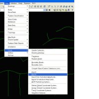
Go to Map>Tools>Export on the menu bar.
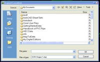
When the Export Location dialog box comes up make sure that the file type is ESRI Shape, select a file name and location and hit OK.
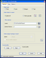
On the selection tab make sure that line is selected and select the way you want Map to find the polylines you want exported. I have choosen to do it by the layer method or you can select manually if the lines or polylines are not on one layer.
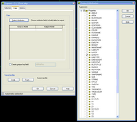
Now go to the data tab and click on the Select Attributes button. This will bring up another window and expand the properties folder and select the property you want to be returned, I have selected the length. You can add other items if you want.
Now just go to the location where the file was saved and open it up the "your File Name.dbf" in Excel. Sum the values under the Length to get a total lengths of the lines or polylines.
There may be an easier way, but this seems fairly quick to do.
Go to Map>Tools>Export on the menu bar.

When the Export Location dialog box comes up make sure that the file type is ESRI Shape, select a file name and location and hit OK.

On the selection tab make sure that line is selected and select the way you want Map to find the polylines you want exported. I have choosen to do it by the layer method or you can select manually if the lines or polylines are not on one layer.
Now go to the data tab and click on the Select Attributes button. This will bring up another window and expand the properties folder and select the property you want to be returned, I have selected the length. You can add other items if you want.
Now just go to the location where the file was saved and open it up the "your File Name.dbf" in Excel. Sum the values under the Length to get a total lengths of the lines or polylines.
Monday, September 25, 2006
Thursday, September 14, 2006
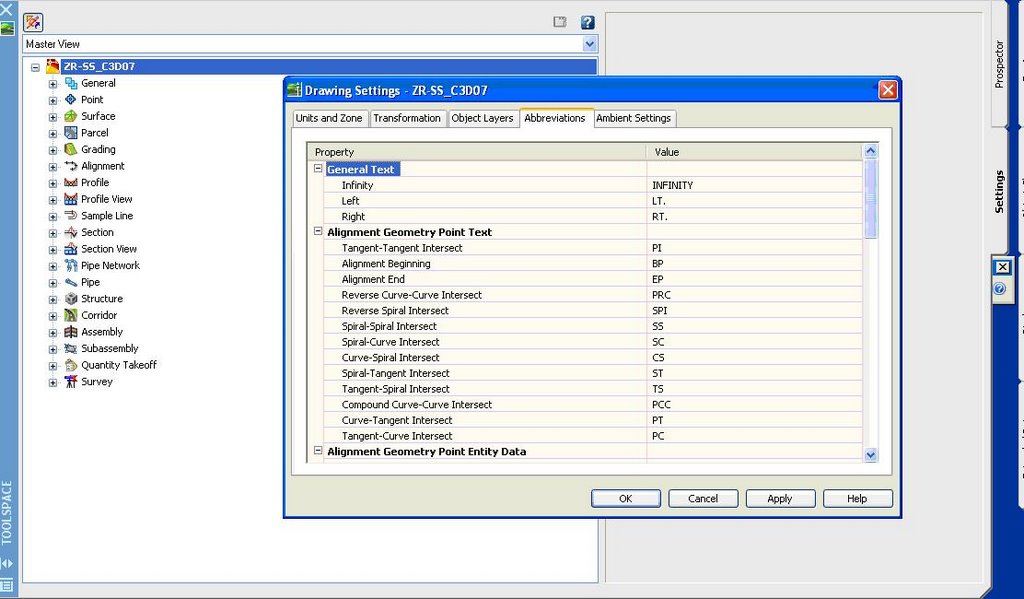
Abbreviations
To change the abbreviations used in labels go to the settings tab of Toolspace and right click on the drawing name and select Edit Drawing Settings. Go to the abbreviations tab and you can change all of the abbreviations in this location for the drawing.

Thursday, September 07, 2006
Tuesday, June 20, 2006
To add a comma to parcel labels go to this web site:
http://civil3drocks.blogspot.com/2006/06/not-so-instant-comma-is-gonna-get-you.html
http://civil3drocks.blogspot.com/2006/06/not-so-instant-comma-is-gonna-get-you.html
Saturday, April 15, 2006
Visualization
Visualization notes from the Webcast
-To show EG and FG surfaces correctly need to use a hide boundary on the EG surface and an outer boundary on the FG. Need to use the same line for each boundary. Not sure on how this will affect FG surfaces which have holes in them since this method hides the EG holes that are in the finish grade surface. May have to create a third surface to show the hole.
(Add picture of hole from project)
-Need to add lane lines to roads. When adding the lane lines include the gaps, to indicate speed through the model. Also need to raise the lines above the road surface. Add 3D blocks for streetlights, trees and other obects.
-Need to add materials to the surfaces/corridors. Can also add pictures via mapping.
Saturday, April 01, 2006
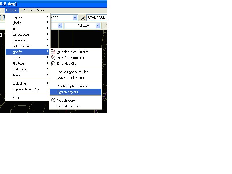
Boundary Trim
Chuck reminded me of this one this past week. Go to Map Menu, Map Tools and choose Boundary Trim. The command lets you trim all objects that cross a polyline you select. Chuck found it very useful for trimming out contours from a base file.
Text to Front
TEXTTOFRONT
Brings all text and dimensions to the front of all the other objects in a drawing.
Brings all text and dimensions to the front of all the other objects in a drawing.
Subscribe to:
Posts (Atom)
LinkWithin
