One of the tasks engineers have to do is Tc calculations. While Civil 3D lets you use label the overall length of a feature line/3DPolyline it does not let you have access to the start and end point elevation of the line. If access was allowed to the start and end point elevations you could use an expression to do the Tc calculations. This post covers how you can calculate the Tc using VBA. The code adds a text label with the Tc value.
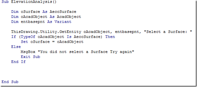
The first thing we need to do is to have the user select a 3DPolyline. The code to do this is shown in the picture below.

Now that we have the 3DPolyline we can process it to get the required information from it.

As shown above getting the ending a starting points is rather easy. The vertices information for a 3DPolyline is contained in the Coordinates part of the object, which is an array type object that starts at 0. The starting elevation is the second value since 0 corresponds to the X value of the first vertex, 1 corresponds to the Y value of the first vertex and 2 corresponds to the Z value of the first vertex. To the the last vertex information we need to determine the number last value in the array. The Ubound() provides that information by giving the number of the last value in the array. The length value of the 3DPolyline is the actual length of the 3DPolyline. Since most methods of Tc was created before widespread use computers the length needed is the 2D length of the line. To get this we need to make a copy of the 3DPolyline and then set all of the Z values in the coordinates array to 0. There may be a better way to do this, but this is the way I thought to do it. If you think you should use the 3D length you skip adding the code below.
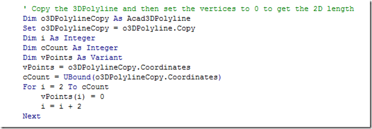
The code takes all of the vertices and adds it to an array then sets the Z values of the vertices to 0. If you can follow patterns you should recognize that every third value is the Z value for a vertex. So that is why at the For i = 2 part of the code it starts at 2 and then process every third value. The Next adds 1 and the i = i +2 has the code move every third value.
So now that we have modified the vertices we need to set the vertices of the copied 3DPolyline to the modified values. The change is done below and the length is gotten and then the copied 3DPolyline is deleted.

Now we need to calculate the slope, but before we do that we need to make sure we get a positive slope (unless you have water that goes up hill). The if then statement does this in the code below. The Tc value is then calculated.
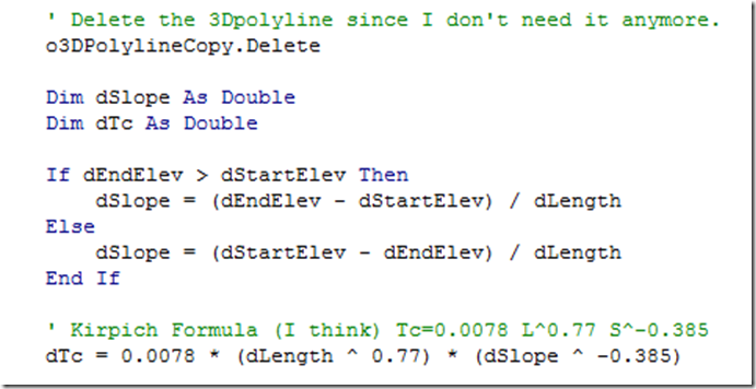
The Tc formula may not be the one you use, or you may have to use different constants contained in the 0.0078 value. So make sure the Tc formula is the one you have to use.
So now that we have a Tc value lets add it to a text label and place it where the user selected the 3DPolyline. The code to do that is below.

The text height is hard coded in the above example, so if you want it to be something else go ahead and change it.
This example assumes you use the waterdrop feature in Civil 3D to generate the line so you can ensure that the 3Dpolyline slopes from a high point to a low point. If you use an alternative method to create the 3DPolyline you may want to add a check to make sure the 3DPolyline slopes in one direction (such as drawing a polyline and then using the surface drape tool). You can also add the other information used in the calculations to the label or export the information to an Excel spreadsheet.
A copy of the completed code may be found on this page of the style site.
